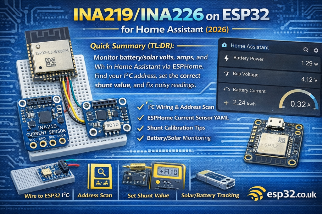
Quick Summary
This guide shows how to connect an INA219 or INA226 current/voltage sensor to an ESP32 over I²C, configure it in ESPHome, and monitor battery/solar voltage, current, power and energy in Home Assistant (optional MQTT). Includes wiring, address scanning, calibration tips, and common fixes for noisy or incorrect readings.
1) INA219 vs INA226 (which one should you use?)
Both sensors measure bus voltage and shunt voltage to calculate current and power.
INA219
- Very common, very cheap breakout boards everywhere
- Great for “good enough” monitoring
- Often found with a 0.1Ω shunt on the board
INA226
- Typically better resolution/accuracy (depends on board + shunt)
- Better choice if you care about small currents and accuracy
- More common in “serious” power monitoring projects
Rule of thumb
- If you already have INA219 boards → use them, they work fine.
- If you’re buying new and want better accuracy → get INA226 + a good shunt.
2) What you need
- ESP32 dev board (DevKitC, etc.)
- INA219 or INA226 breakout board
- Jumper wires
- Optional: a known load (e.g., 5W/10W resistor, DC lamp, USB load tester) for calibration
3) Wiring (ESP32 ↔ INA219/INA226 over I²C)
3.1 I²C wiring (recommended defaults)
Use the ESP32 default I²C pins:
| INA219/INA226 | ESP32 |
|---|---|
| VCC | 3V3 |
| GND | GND |
| SDA | GPIO21 |
| SCL | GPIO22 |
Power the breakout from 3.3V so the I²C logic levels match the ESP32.
3.2 “Where does the sensor go” in the power line?
Both sensors measure current through a shunt. Typical breakout boards place the shunt on board between two screw terminals.
You’ll see terminals labelled something like:
- VIN+ / VIN- (or V+ / V-)
You wire it in series with the positive line:
- Battery/Solar positive → VIN+
- VIN- → your load/system positive
- Battery/Solar negative stays common ground (but see the note below)
3.3 Very important: common ground
For stable readings:
- The ESP32 ground and the system ground should be common (shared), unless you’re using isolation elsewhere.
If you’re doing solar/battery monitoring of a floating system and you’re unsure, start with a simple shared ground test setup first.
4) Find the I²C address (scan it first)
Many boards use:
- INA219: often 0x40
- INA226: often 0x40 as well (but varies)
Use this ESPHome i2c scan config and check logs:
i2c:
  sda: 21
  scl: 22
  scan: true
Then in ESPHome logs you’ll see detected devices and their addresses.
5) ESPHome configuration (Home Assistant native)
5.1 Base ESPHome template
esphome:
  name: esp32-ina-monitor
  friendly_name: ESP32 INA Monitoresp32:
  board: esp32dev
  framework:
    type: arduinologger:
api:
ota:wifi:
  ssid: !secret wifi_ssid
  password: !secret wifi_password
  ap:
    ssid: "INA Monitor Fallback"
    password: !secret ap_passwordcaptive_portal:i2c:
  sda: 21
  scl: 22
  scan: true
6) INA219 in ESPHome (recommended config)
sensor:
  - platform: ina219
    address: 0x40
    shunt_resistance: 0.1 ohm
    current:
      name: "Battery Current"
    power:
      name: "Battery Power"
    bus_voltage:
      name: "Bus Voltage"
    shunt_voltage:
      name: "Shunt Voltage"
    max_voltage: 32.0V
    max_current: 3.2A
    update_interval: 2s
Notes
shunt_resistancemust match your board’s actual shunt.- Many INA219 breakouts are 0.1Ω, but not all. Some use 0.01Ω.
- If your current readings are “10× off”, this is usually why.
max_voltageandmax_currenthelp calibration range choices.- 2 seconds is a nice interval for dashboards; use 5–10s for low-noise logging.
7) INA226 in ESPHome (recommended config)
sensor:
  - platform: ina226
    address: 0x40
    shunt_resistance: 0.01 ohm
    current:
      name: "Battery Current"
    power:
      name: "Battery Power"
    bus_voltage:
      name: "Bus Voltage"
    shunt_voltage:
      name: "Shunt Voltage"
    update_interval: 2s
Notes
- INA226 boards often come with lower-value shunts like 0.01Ω.
- Again: wrong shunt value = wrong current.
8) Energy tracking (Wh / kWh) in Home Assistant
INA sensors provide power (W). To track energy (Wh/kWh) you integrate power over time.
In ESPHome, add a total_daily_energy sensor:
sensor:
  - platform: ina219
    address: 0x40
    shunt_resistance: 0.1 ohm
    power:
      name: "Battery Power"
      id: batt_power
    current:
      name: "Battery Current"
    bus_voltage:
      name: "Bus Voltage"
    update_interval: 2s  - platform: total_daily_energy
    name: "Daily Energy"
    power_id: batt_power
    unit_of_measurement: "Wh"
Then add it to the Energy Dashboard (usually you’ll want kWh; you can convert in HA using a template helper if needed).
9) Calibration and accuracy tips (the stuff that makes it “trustworthy”)
9.1 Verify your shunt value
Look at the shunt resistor marking:
- “R100” → 0.1Ω
- “R010” → 0.01Ω
- “R005” → 0.005Ω
If you can’t read it or don’t trust the listing:
- Measure it with a meter that can measure low resistance (or do a voltage drop test with known current).
9.2 Use a known load
For a sanity check:
- Connect a known resistive load (e.g., 10Ω at 12V ≈ 1.2A)
- Compare INA reading vs multimeter
Adjust shunt value and/or scaling if needed.
9.3 Smooth noisy readings
If you see jitter:
- Increase
update_intervalto 5s - Add a sliding window average filter in ESPHome:
filters:
  - sliding_window_moving_average:
      window_size: 6
      send_every: 3
Use it on current/power sensors.
10) Common problems & fixes
Problem: current reading is ~10x too high/low
Cause: wrong shunt_resistance value.
Fix: set the correct shunt resistance for your board.
Problem: voltage looks right, current is 0A
Cause:
- sensor not placed in series correctly (VIN+ and VIN- swapped / load wired wrong)
- no load current flowing
Fix: re-check wiring direction and series placement.
Problem: I²C device not found
Cause:
- wrong SDA/SCL pins
- no common ground
- wrong address
- powered at 5V with no level shifting
Fix:
- enable
scan: trueand check logs - power the module at 3.3V
- check solder joints on cheap boards
Problem: unstable readings when Wi-Fi transmits
Cause: power noise / ground bounce.
Fix:
- add decoupling near ESP32 and sensor (0.1µF + 10µF)
- reduce update rate
- keep wiring short
11) Solar/Battery monitoring patterns that work well
Pattern A: monitor the load side of a battery system
- Battery → INA → load
- Use sensors:
- Bus Voltage = battery/system voltage
- Current = load current
- Power = load power
- Daily energy = Wh used per day
Pattern B: monitor charge current from solar controller
Put INA in series with the line you want to measure:
- Controller output → INA → battery
This gives you “charge current” rather than “load current”.
Don’t try to measure “everything” with one INA unless your wiring makes that physically true.
12) MQTT option (optional)
If you prefer MQTT:
mqtt:
  broker: 192.168.1.10
  username: !secret mqtt_user
  password: !secret mqtt_pass
Most ESPHome + Home Assistant users stick with the native API, but MQTT is fine for broker-centric setups.