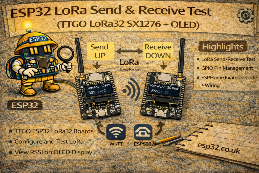
This project shows how to do a simple LoRa “Hello World” send & receive test using two TTGO LoRa32 (SX1276) boards with built-in 0.96″ SSD1306 OLED displays.
We’ll configure one board as a sender, which sends a counter every second, and another board as a receiver, which displays the received message and RSSI (signal strength) on its OLED and on the Serial Monitor.
1. Hardware Required
You’ll need:
- 2 × TTGO LoRa32 SX1276 boards (with integrated OLED)
- 2 × Micro-USB cables
- A computer with Arduino IDE installed
The code below assumes the typical TTGO LoRa32 pinout:
- LoRa SPI pins
- SCK → GPIO 5
- MISO → GPIO 19
- MOSI → GPIO 27
- SS (NSS) → GPIO 18
- RST → GPIO 14
- DIO0 → GPIO 26
- OLED pins
- SDA → GPIO 4
- SCL → GPIO 15
- RST → GPIO 16
2. Frequency Band
The sketch uses:
#define BAND 866E6
This is the 866 MHz band (Europe).
If you are in a different region, use the appropriate value:
- 433E6 – Asia (433 MHz)
- 866E6 – Europe (866 MHz)
- 915E6 – North America (915 MHz)
Both sender and receiver must use the same BAND.
3. Arduino IDE Setup
- Install ESP32 Board Support
- In Arduino IDE:
File → Preferences → Additional Boards Manager URLs:
Add:https://dl.espressif.com/dl/package_esp32_index.json - Then:
Tools → Board → Boards Manager…
Search for “esp32” and install “esp32 by Espressif Systems”.
- In Arduino IDE:
- Select the Board
Tools → Board → ESP32 Arduino → TTGO LoRa32-OLED V1
(or similar; choose the appropriate TTGO/ESP32 board if listed.)
- Install Required Libraries
- LoRa by Sandeep Mistry
- Adafruit GFX Library
- Adafruit SSD1306
Tools → Manage Libraries…and search for each by name.
4. LoRa Sender Sketch
Upload this code to the first TTGO LoRa32 (the sender).
It sends "hello <counter>" once per second and shows the counter on the OLED.
/*********
  Rui Santos
  Complete project details at https://RandomNerdTutorials.com/ttgo-lora32-sx1276-arduino-ide/
*********/

//Libraries for LoRa
#include <SPI.h>
#include <LoRa.h>

//Libraries for OLED Display
#include <Wire.h>
#include <Adafruit_GFX.h>
#include <Adafruit_SSD1306.h>

//define the pins used by the LoRa transceiver module
#define SCK 5
#define MISO 19
#define MOSI 27
#define SS 18
#define RST 14
#define DIO0 26

//433E6 for Asia
//866E6 for Europe
//915E6 for North America
#define BAND 866E6

//OLED pins
#define OLED_SDA 4
#define OLED_SCL 15
#define OLED_RST 16
#define SCREEN_WIDTH 128 // OLED display width, in pixels
#define SCREEN_HEIGHT 64 // OLED display height, in pixels

//packet counter
int counter = 0;

Adafruit_SSD1306 display(SCREEN_WIDTH, SCREEN_HEIGHT, &Wire, OLED_RST);

void setup() {
  //initialize Serial Monitor
  Serial.begin(115200);

  //reset OLED display via software
  pinMode(OLED_RST, OUTPUT);
  digitalWrite(OLED_RST, LOW);
  delay(20);
  digitalWrite(OLED_RST, HIGH);

  //initialize OLED
  Wire.begin(OLED_SDA, OLED_SCL);
  if(!display.begin(SSD1306_SWITCHCAPVCC, 0x3c, false, false)) { // Address 0x3C for 128x32
    Serial.println(F("SSD1306 allocation failed"));
    for(;;); // Don't proceed, loop forever
  }

  display.clearDisplay();
  display.setTextColor(WHITE);
  display.setTextSize(2);
  display.setCursor(0,0);
  display.print("LORA SENDER ");
  display.display();

  Serial.println("LoRa Sender Test");

  //SPI LoRa pins
  SPI.begin(SCK, MISO, MOSI, SS);
  //setup LoRa transceiver module
  LoRa.setPins(SS, RST, DIO0);

  if (!LoRa.begin(BAND)) {
    Serial.println("Starting LoRa failed!");
    while (1);
  }
  Serial.println("LoRa Initializing OK!");
  display.setCursor(0,10);
  display.print("LoRa Initializing OK!");
  display.display();
  delay(2000);
}

void loop() {
  Serial.print("Sending packet: ");
  Serial.println(counter);

  //Send LoRa packet to receiver
  LoRa.beginPacket();
  LoRa.print("hello ");
  LoRa.print(counter);
  LoRa.endPacket();

  display.clearDisplay();
  display.setCursor(0,0);
  display.setTextSize(2);
  display.print("Counter: ");
  display.print(counter);
  display.display();

  counter++;

  delay(1000);
}
What this sketch does:
- Initializes the OLED and prints “LORA SENDER” and “LoRa Initializing OK!”
- Configures LoRa with the selected band and pins.
- In the
loop():- Prints the counter on the Serial Monitor.
- Sends
"hello <counter>"via LoRa. - Updates the OLED display showing the current counter value.
- Increments the counter every second.
5. LoRa Receiver Sketch
Upload this code to the second TTGO LoRa32 (the receiver).
It listens for packets, prints them to Serial, and shows the last message and RSSI on the OLED.
/*********
  Rui Santos
  Complete project details at https://RandomNerdTutorials.com/ttgo-lora32-sx1276-arduino-ide/
*********/

//Libraries for LoRa
#include <SPI.h>
#include <LoRa.h>

//Libraries for OLED Display
#include <Wire.h>
#include <Adafruit_GFX.h>
#include <Adafruit_SSD1306.h>

//define the pins used by the LoRa transceiver module
#define SCK 5
#define MISO 19
#define MOSI 27
#define SS 18
#define RST 14
#define DIO0 26

//433E6 for Asia
//866E6 for Europe
//915E6 for North America
#define BAND 866E6

//OLED pins
#define OLED_SDA 4
#define OLED_SCL 15
#define OLED_RST 16
#define SCREEN_WIDTH 128 // OLED display width, in pixels
#define SCREEN_HEIGHT 64 // OLED display height, in pixels

Adafruit_SSD1306 display(SCREEN_WIDTH, SCREEN_HEIGHT, &Wire, OLED_RST);

String LoRaData;

void setup() {
  //initialize Serial Monitor
  Serial.begin(115200);

  //reset OLED display via software
  pinMode(OLED_RST, OUTPUT);
  digitalWrite(OLED_RST, LOW);
  delay(20);
  digitalWrite(OLED_RST, HIGH);

  //initialize OLED
  Wire.begin(OLED_SDA, OLED_SCL);
  if(!display.begin(SSD1306_SWITCHCAPVCC, 0x3c, false, false)) { // Address 0x3C for 128x32
    Serial.println(F("SSD1306 allocation failed"));
    for(;;); // Don't proceed, loop forever
  }

  display.clearDisplay();
  display.setTextColor(WHITE);
  display.setTextSize(2);
  display.setCursor(0,0);
  display.display();

  //SPI LoRa pins
  SPI.begin(SCK, MISO, MOSI, SS);
  //setup LoRa transceiver module
  LoRa.setPins(SS, RST, DIO0);

  if (!LoRa.begin(BAND)) {
    Serial.println("Starting LoRa failed!");
    while (1);
  }
  Serial.println("LoRa Initializing OK!");
  display.setCursor(0,10);
  display.display();
}

void loop() {

  //try to parse packet
  int packetSize = LoRa.parsePacket();
  if (packetSize) {
    //received a packet
    Serial.print("Received packet ");

    //read packet
    while (LoRa.available()) {
      LoRaData = LoRa.readString();
      Serial.print(LoRaData);
    }

    //print RSSI of packet
    int rssi = LoRa.packetRssi();
    Serial.print(" with RSSI ");
    Serial.println(rssi);

    // Display information
    display.clearDisplay();
    display.setCursor(0,0);
    display.setCursor(0,20);
    display.setCursor(0,00);
    display.print(LoRaData);
    display.setCursor(0,40);
    display.print("RSSI: ");
    display.print(rssi);
    display.display();
  }
}
What this sketch does:
- Initializes the OLED and LoRa radio exactly as the sender.
- In the
loop():- Calls
LoRa.parsePacket()to check if a packet was received. - If a packet is available:
- Reads the entire payload into
LoRaData. - Prints the received string and its RSSI on the Serial Monitor.
- Displays:
- The received text (e.g.
hello 42) on the OLED. - The packet RSSI (e.g.
RSSI: -85).
- The received text (e.g.
- Reads the entire payload into
- Calls
6. Uploading & Testing
- Connect the sender board via USB.
- Select the correct port in Arduino IDE.
- Upload the sender sketch.
- Open Serial Monitor at 115200 baud to watch sent packets.
- Connect the receiver board via USB.
- Select its port.
- Upload the receiver sketch.
- Open another Serial Monitor at 115200 baud (or use two IDE windows).
- Place the two boards a few meters apart (or more) and power them both.
You should see:
- Sender Serial Monitor:
Sending packet: 0Sending packet: 1Sending packet: 2… - Receiver Serial Monitor:
Received packet hello 0 with RSSI -45Received packet hello 1 with RSSI -46Received packet hello 2 with RSSI -47… - Receiver OLED:
Top line:hello <counter>
Bottom line:RSSI: <value>
If nothing appears on the receiver:
- Check Frequency Band
- Both sketches must use the same BAND (
866E6in this example).
- Both sketches must use the same BAND (
- Check Board Selection & Port
- Verify correct board and COM port are selected for each TTGO.
- Antenna
- Make sure each TTGO has its LoRa antenna connected.
- Never transmit LoRa without an antenna, you can damage the RF stage.
- Libraries & Versions
- Confirm LoRa, Adafruit GFX, and Adafruit SSD1306 are installed and up to date.
- If the OLED shows nothing, double-check I²C address (
0x3C) and pins.
- Serial Monitor Baud Rate
- Must be set to
115200to matchSerial.begin(115200);.
- Must be set to
8. Next Steps
Once your basic LoRa send/receive test works, you can extend this setup to:
- Send sensor data (temperature, humidity, etc.) instead of a simple counter.
- Add a node ID in the payload and build a small multi-node LoRa network.
- Integrate with ESP32 deep sleep to build low-power battery-powered nodes.
- Forward data from the receiver to MQTT / Home Assistant / InfluxDB.