This guide explains the ESP32-C6 DevKitC-1 v1.2 pinout, showing which GPIOs are safe ,which affect boot or native USB and how to pick pins for ADC, I²C, SPI, UART, and the RGB LED.
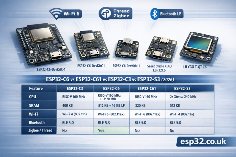
The ESP32-C6-DevKitC-1 v1.2 is Espressif’s entry-level board for the ESP32-C6-WROOM-1/1U module – a Wi-Fi 6 + BLE 5 + 802.15.4 (Thread/Zigbee) SoC with RISC-V core and 8 MB flash.
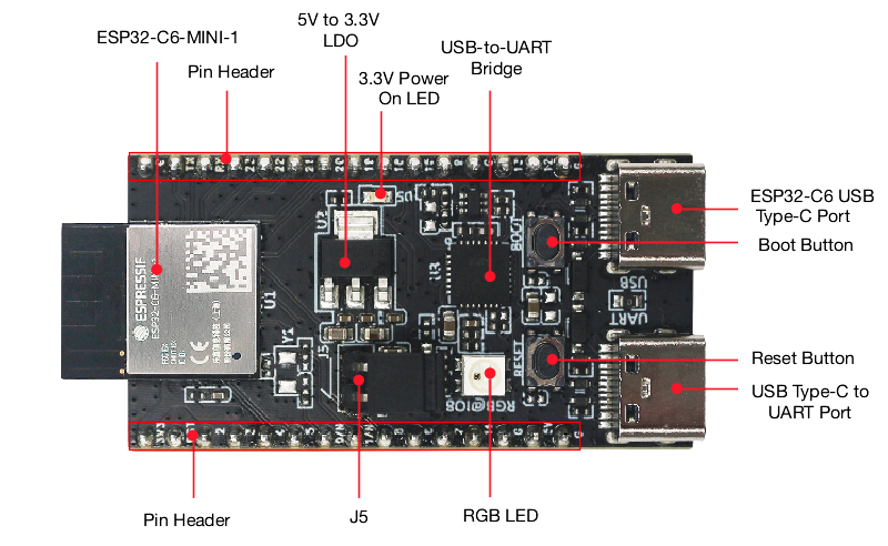
1. Board overview (DevKitC-1 v1.2)
Key hardware bits:
- Module: ESP32-C6-WROOM-1 or -1U (8 MB SPI flash, PCB or external antenna)
- USB:
- USB-to-UART Type-C port (left)
- Native ESP32-C6 USB Type-C port (right – USB 2.0 FS, USB-Serial/JTAG)
- Power regulation: 5 V → 3.3 V LDO
- J1/J3 pin headers: all GPIOs except internal flash bus broken out
- BOOT button (enter download mode)
- RESET (RST/EN) button
- RGB WS2812 LED on GPIO8
- J5 jumper for current measurement
All GPIOs are 3.3 V only (not 5-V tolerant). Use level shifting for 5-V peripherals.
2. Header pinout (J1 and J3)
From Espressif’s v1.2 user guide:
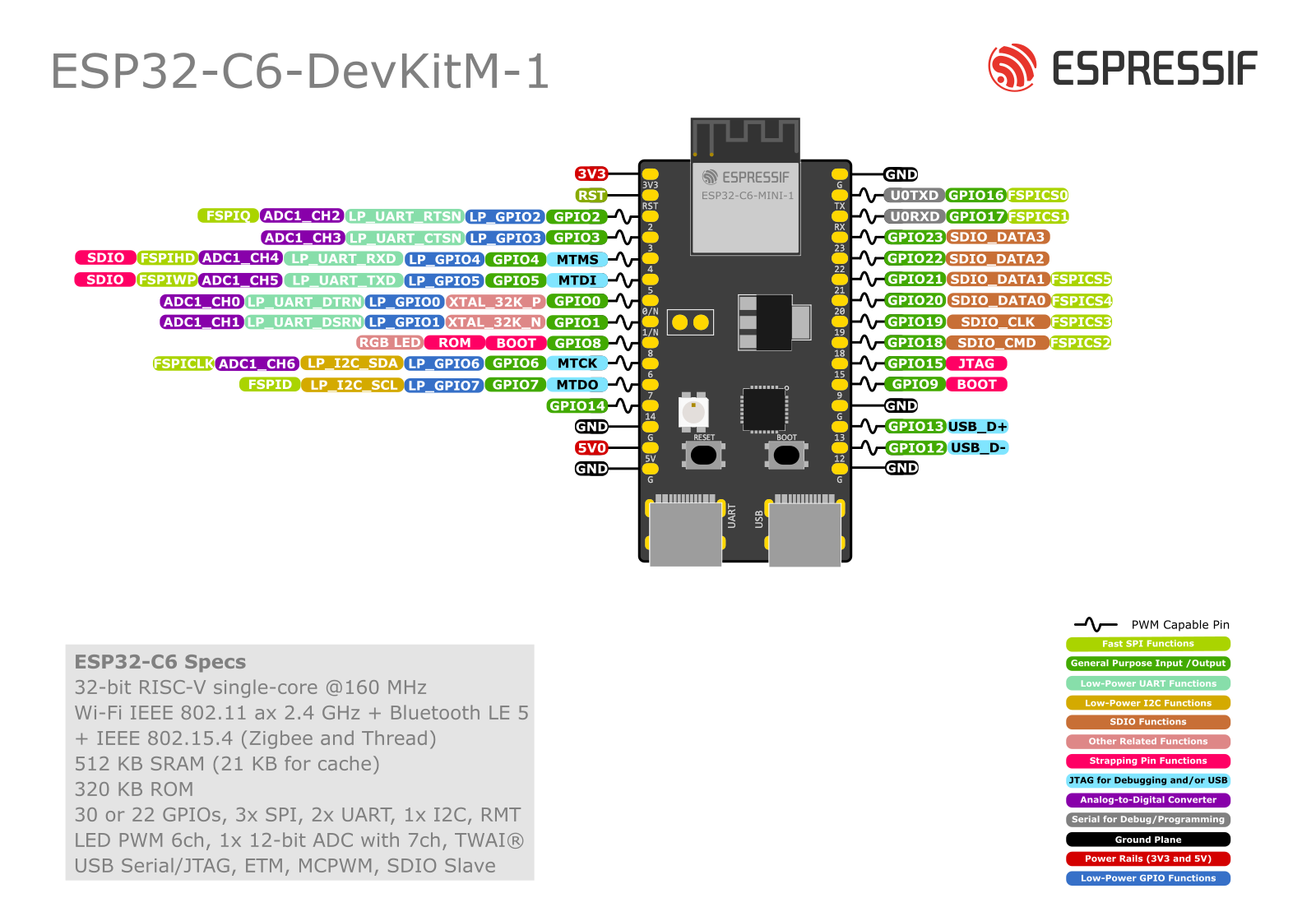
J1 (left header, top→bottom as in docs)
| J1 No. | Name | Main functions (short list) |
|---|---|---|
| 1 | 3V3 | 3.3 V supply |
| 2 | RST | EN / CHIP_PU – high = enable, low = reset |
| 3 | – | (reserved in table, no pin name) |
| 4 | 4 | MTMS, GPIO4, LP_GPIO4, ADC1_CH4, FSPIHD |
| 5 | 5 | MTDI, GPIO5, LP_GPIO5, ADC1_CH5, FSPIWP |
| 6 | 6 | MTCK, GPIO6, LP_GPIO6, LP_I2C_SDA, ADC1_CH6, FSPICLK |
| 7 | 7 | MTDO, GPIO7, LP_GPIO7, LP_I2C_SCL, FSPID |
| 8 | 0 | GPIO0, XTAL_32K_P, LP_GPIO0, ADC1_CH0 |
| 9 | 1 | GPIO1, XTAL_32K_N, LP_GPIO1, ADC1_CH1 |
| 10 | 8 | GPIO8 – drives RGB LED |
| 11 | 10 | GPIO10 |
| 12 | 11 | GPIO11 |
| 13 | 2 | GPIO2, LP_GPIO2, ADC1_CH2, FSPIQ |
| 14 | 3 | GPIO3, LP_GPIO3, ADC1_CH3 |
| 15 | 5V | 5 V supply (from USB or external) |
| 16 | G | Ground |
| 17 | NC | Not connected |
J3 (right header, top→bottom)
| J3 No. | Name | Main functions |
|---|---|---|
| 1 | G | Ground |
| 2 | TX | U0TXD, GPIO16, FSPICS0 |
| 3 | RX | U0RXD, GPIO17, FSPICS1 |
| 4 | 15 | GPIO15 |
| 5 | 23 | GPIO23, SDIO_DATA3 |
| 6 | 22 | GPIO22, SDIO_DATA2 |
| 7 | 21 | GPIO21, SDIO_DATA1, FSPICS5 |
| 8 | 20 | GPIO20, SDIO_DATA0, FSPICS4 |
| 9 | 19 | GPIO19, SDIO_CLK, FSPICS3 |
| 10 | 18 | GPIO18, SDIO_CMD, FSPICS2 |
| 11 | 9 | GPIO9 |
| 12 | G | Ground |
| 13 | 13 | GPIO13, USB_D+ |
| 14 | 12 | GPIO12, USB_D− |
| 15 | G | Ground |
| 16 | NC | Not connected |
Strapping and special roles are described below.
3. Strapping pins – affect boot
ESP32-C6 uses several pins as strapping pins, sampled at reset to decide boot config. On this board:
Strapping pins:
GPIO4 (MTMS),GPIO5 (MTDI),GPIO8,GPIO9,GPIO15
These control things like:
- boot mode (flash vs UART download)
- ROM log output
- internal regulator/flash options
Practical rules:
- Don’t hard-pull these pins low or high with strong external circuits at reset.
- Avoid big capacitors, low-value resistors to GND, or weird level shifters on them.
- You can use them after boot for normal I/O, but for beginners it’s simpler to avoid 4, 5, 8, 9, 15 for critical sensors/relays.
GPIO8 drives the RGB LED; the board’s resistor network is already designed not to break boot.
4. Safe GPIOs for everyday use
From the header tables plus strapping notes, a nice “safe pool” of GPIOs for digital I/O is:
0, 1, 2, 3, 6, 7, 10, 11, 16, 17, 18, 19, 20, 21, 22, 23
These:
- have no boot-strapping side effects (except 6/7 are fine in normal use)
- aren’t tied to USB D± (12/13)
- aren’t hard-wired to the RGB LED (8)
Notes:
- GPIO16/17 (TX/RX) are used by the USB-to-UART bridge; best to keep them for Serial console/flashing.
- GPIO18–23 double as SDIO / extra SPI CS pins, but for most projects they’re just perfectly good GPIOs.
5. ADC pins
ESP32-C6 has a 12-bit ADC with 8 channels. According to Espressif + community pinouts:
- ADC1 channels:
- GPIO0 → ADC1_CH0
- GPIO1 → ADC1_CH1
- GPIO2 → ADC1_CH2
- GPIO3 → ADC1_CH3
- GPIO4 → ADC1_CH4
- GPIO5 → ADC1_CH5
- GPIO6 → ADC1_CH6
- (GPIO7 is often used as digital only in docs; check your SDK’s mapping if you need all 8)
Some third-party guides also list GPIO9 as ADC2, but Espressif’s official docs focus on ADC1 on 0–6.
Best practice:
- For simple sensors, stick to GPIO0–3, 4, 6.
- Avoid GPIO4 & 5 if you don’t like touching strapping pins; or use them only with high-value resistor dividers that don’t “fight” the boot levels.
- Keep input voltage ≤ 3.3 V (or less, depending on attenuation you configure).
Example (Arduino-style):
const int ADC_PIN = 3; // GPIO3

void setup() {
  Serial.begin(115200);
  analogReadResolution(12);
}

void loop() {
  int raw = analogRead(ADC_PIN);
  float volts = raw * 3.3f / 4095.0f;
  Serial.printf("ADC raw=%d  V=%.2f\n", raw, volts);
  delay(500);
}
6. RGB LED on GPIO8
The DevKitC-1 includes a WS2812 addressable RGB LED connected to GPIO8.
- Use
Adafruit_NeoPixelorFastLEDwith data pin = 8. - It’s great for Wi-Fi status, errors, etc.
- GPIO8 is a strapping pin, but the onboard circuit is already tuned; you just shouldn’t hang extra heavy loads on that pin.
Minimal example:
#include <Adafruit_NeoPixel.h>

#define LED_PIN   8
#define LED_COUNT 1

Adafruit_NeoPixel rgb(LED_COUNT, LED_PIN, NEO_GRB + NEO_KHZ800);

void setup() {
  rgb.begin();
  rgb.show(); // off
}

void loop() {
  rgb.setPixelColor(0, rgb.Color(255, 0, 0)); // red
  rgb.show();
  delay(300);
  rgb.setPixelColor(0, rgb.Color(0, 255, 0)); // green
  rgb.show();
  delay(300);
  rgb.setPixelColor(0, rgb.Color(0, 0, 255)); // blue
  rgb.show();
  delay(300);
}
7. USB (native) vs USB-UART
This board is slightly unusual: it has two USB-C ports.
- USB-to-UART Type-C (“UART”)
- Uses a USB-UART bridge chip.
- Connected to GPIO16 (TX) and GPIO17 (RX).
- Ideal for classic Serial flashing (
esptool.py, Arduino) and Serial Monitor.
- ESP32-C6 native USB Type-C (“USB”)
- Connected directly to GPIO12 (USB_D−) and GPIO13 (USB_D+).
- Supports USB-Serial/JTAG, CDC, HID, etc.
- When using native USB, treat GPIO12/13 as dedicated USB pins – don’t connect other circuitry.
DON’T use GPIO12/13 for anything except USB if you rely on native USB.
8. I²C pins
ESP32-C6’s I²C is fully routed via the GPIO matrix, so you can choose almost any free GPIO.
Nice, conflict-free combos on this board:
- Option A (recommended):
- SDA = GPIO6 (J1-6)
- SCL = GPIO7 (J1-7)
- Option B (if 6/7 are busy):
- SDA = GPIO0
- SCL = GPIO1
Avoid using strapping pins (4, 5, 8, 9, 15) or USB D± (12, 13) for I²C unless you know exactly what you’re doing.
Example (Arduino):
#include <Wire.h>

void setup() {
  Wire.begin(6, 7); // SDA=GPIO6, SCL=GPIO7
  Serial.begin(115200);
  Serial.println("I2C on GPIO6 (SDA) / GPIO7 (SCL)");
}
9. SPI pins
ESP32-C6 has multiple SPI controllers; the internal flash bus is separate. User SPI can be mapped to most GPIOs, but the FSPI-labeled pins are convenient:
Good SPI mapping on ESP32-C6-DevKitC-1:
- SCLK = GPIO6 (FSPICLK, J1-6)
- MOSI = GPIO7 (FSPID, J1-7)
- MISO = GPIO2 or GPIO4 (FSPIQ / FSPIHD, J1-13 or J1-4)
- CS = GPIO10 (FSPICS0 equivalent, J1-11 or alternative CS on 16–23)
Typical example:
// Example DC/CS assignments for a display or SPI sensor
#define PIN_SPI_SCLK  6
#define PIN_SPI_MOSI  7
#define PIN_SPI_MISO  2
#define PIN_SPI_CS    10
Because C6’s SPI is IO-matrixed, you can move these around if needed – just avoid USB D± and be cautious with strapping pins.
10. UART / Serial ports
- UART0 is connected via the USB-UART bridge to GPIO16 (TX) / GPIO17 (RX) on J3.
- This is the default
Serialin Arduino / ESP-IDF logging.
- This is the default
- Additional UARTs can be mapped to other GPIOs (e.g., 18/19 for RS-485 or GPS).
Example second UART:
HardwareSerial Serial1(1);

void setup() {
  Serial.begin(115200);                      // USB-UART on 16/17
  Serial1.begin(9600, SERIAL_8N1, 19, 18);  // RX=19, TX=18
}
11. Quick pin recipes
11.1 Classic Wi-Fi sensor node (I²C + ADC + RGB status)
Suggested mapping:
| Function | GPIO | Notes |
|---|---|---|
| I²C SDA | 6 | J1-6, safe, also ADC1_CH6 |
| I²C SCL | 7 | J1-7 |
| Analog sensor | 0 | ADC1_CH0 |
| Extra digital in | 2 | Button / reed switch |
| Extra digital out | 10 | Relay / MOSFET |
| RGB LED | 8 | On-board WS2812 |
All of these avoid USB D± and keep strapping pins mostly untouched during boot.
11.2 Thread/Zigbee border router base
If you mostly care about radio + status LED:
- Leave most GPIOs free.
- Use GPIO8 for RGB, GPIO6/7 if you add I²C sensors later.
- Keep UART on 16/17 for logs.
12. Cheat-sheet summary
- Safest digital GPIOs:
0, 1, 2, 3, 6, 7, 10, 11, 16, 17, 18, 19, 20, 21, 22, 23 - Avoid (boot / special):
4, 5, 8, 9, 15 are strapping pins – only use if you know the boot implications. - USB pins:
12 (USB_D−), 13 (USB_D+) – keep for native USB only. - ADC:
Best on 0–3, 4, 5, 6 (ADC1 channels). - I²C default:
SDA = 6, SCL = 7 - SPI default:
SCLK = 6, MOSI = 7, MISO = 2/4, CS = 10 - Onboard RGB LED:
GPIO8 (WS2812).
Follow this map and the ESP32-C6-DevKitC-1 v1.2 becomes a very predictable board for Wi-Fi 6 / BLE / Thread projects, without the usual “why won’t it boot / flash / show up on USB?” headaches.