
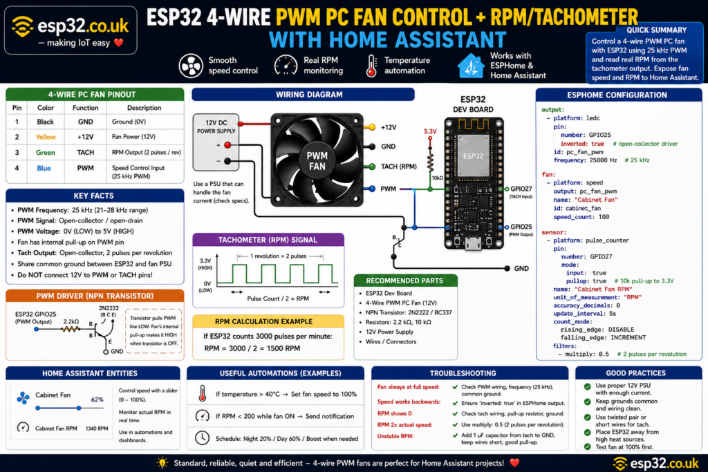
A standard 4-wire PWM PC fan can be controlled from an ESP32 while its real rotational speed is returned to Home Assistant as RPM. The fan keeps its normal 12 V supply continuously connected, while the ESP32 generates the standard 25 kHz PWM control signal through a small transistor or MOSFET. The fan’s tachometer output is read by another ESP32 GPIO and converted to RPM. ESPHome can then expose both a percentage-controlled fan entity and a live RPM sensor in Home Assistant.
1. Why use a 4-wire PC fan with an ESP32?
PC fans are inexpensive, quiet, reliable and available in almost every useful size:
- 40 mm
- 60 mm
- 80 mm
- 92 mm
- 120 mm
- 140 mm
- larger industrial sizes
A 4-wire PWM fan is particularly useful because speed is controlled separately from the fan’s power supply.
The four wires provide:
- Ground
- Fan power
- Tachometer / RPM output
- PWM speed-control input
The fan receives continuous power while its internal electronics control motor speed according to the PWM signal. This is preferable to repeatedly switching the 12 V supply on and off to control speed.
With an ESP32 and ESPHome, this makes it possible to build Home Assistant-controlled ventilation for:
- network cabinets
- AV cabinets
- server racks
- greenhouses
- electronics enclosures
- 3D-printer cabinets
- home ventilation
- radiators
- solar/battery cabinets
- workshops
Home Assistant can control fan speed from 0–100% while simultaneously monitoring whether the fan is actually spinning.
2. 4-wire PC fan pinout
The standard PC PWM fan connector uses the following functions:
| Pin | Typical wire colour | Function |
|---|---|---|
| 1 | Black | Ground |
| 2 | Yellow | Fan power |
| 3 | Green | Tachometer / RPM |
| 4 | Blue | PWM control |
These colours are widely used, but always check the fan datasheet because manufacturers can use different wire colours. Noctua documents the same standard pin assignment and notes that the scheme follows the Intel/AMD fan standard.
Most normal PC fans use 12 V, although 5 V and 24 V four-wire fans also exist.
Do not assume the fan supply voltage from the connector alone.
3. The important difference between 3-wire and 4-wire fans
A 3-wire fan normally provides:
- Ground
- Power
- Tachometer
There is no dedicated speed-control wire.
Speed therefore usually has to be controlled by changing the fan’s supply voltage.
A 4-wire fan adds the dedicated PWM control input.
The fan can remain connected to its normal supply voltage while the PWM signal tells the internal fan controller how fast to run.
This is exactly what PC motherboards do.
The ESP32 can imitate that motherboard fan-control signal.
4. Do not power a 12 V fan from the ESP32
The ESP32 should not supply the fan’s motor power.
A typical arrangement is:
12 V PSU +  ───────────── Fan +12 V

12 V PSU GND ──────┬──── Fan GND
                   │
                   └──── ESP32 GND

ESP32 GPIO ── driver ─── Fan PWM

Fan TACH ─────────────── ESP32 GPIO
The fan gets power directly from an appropriate external supply.
The ESP32 and fan supply must share common ground so that the PWM and tachometer signals have the same electrical reference. Noctua specifically identifies missing common ground as a cause of unreliable PWM control.
Choose a power supply capable of comfortably handling the fan’s rated current and startup current.
5. PC fan PWM uses approximately 25 kHz
The PWM input on a standard 4-wire PC fan is not the low-frequency PWM commonly used in beginner Arduino LED examples.
The target frequency is:
25 kHz
The accepted range in the Intel-style specification is approximately:
21–28 kHz
with 25 kHz being the intended operating point.
This frequency is high enough that the switching itself is outside normal audible range.
The ESP32’s hardware LEDC PWM peripheral can easily generate 25 kHz; ESPHome’s LEDC output supports configurable PWM frequencies over a much wider range.
6. Do not connect the PWM pin like a normal LED
This is one of the most important parts of the project.
The standard fan PWM input is designed around an open-collector/open-drain control signal.
The fan already contains its own pull-up on the PWM input. A controller is expected primarily to pull that line LOW rather than drive it HIGH directly. Noctua’s PWM documentation likewise notes that an external pull-up is unnecessary because the fan contains its own internal pull-up.
The safest interface is therefore a small transistor.
7. Recommended PWM driver circuit
A simple NPN transistor such as:
- 2N2222
- PN2222
- BC547
- BC337
works well.
Typical circuit:
ESP32 GPIO25
     │
   2.2 kΩ
     │
    BASE
     │
   2N2222
     │
COLLECTOR ───────── Fan PWM
     │
 EMITTER
     │
    GND
The ESP32 drives the transistor.
The transistor then pulls the fan’s PWM input to ground.
No connection from 12 V to the PWM pin is required.
In fact, 12 V must never be connected to the fan’s PWM input. Noctua’s published PWM specification warns that applying the fan supply voltage to the PWM input can damage the fan.
8. A small N-channel MOSFET can also be used
Instead of an NPN transistor, a small N-channel MOSFET can provide an open-drain interface.
Suitable examples include devices such as:
- 2N7000
- 2N7002
- BSS138
Typical wiring:
ESP32 GPIO25 ───── Gate

Fan PWM ────────── Drain

GND ────────────── Source
A small gate resistor, for example 100–330 Ω, can be added if desired.
The advantage is that essentially no steady GPIO current is required.
9. Why the PWM output must be inverted
The transistor creates an electrical inversion.
When the ESP32 GPIO goes HIGH:
Transistor ON
→ PWM pin pulled LOW
When the ESP32 GPIO goes LOW:
Transistor OFF
→ fan internal pull-up makes PWM HIGH
So the ESP32’s physical signal is the inverse of the signal that reaches the fan.
ESPHome can compensate automatically by configuring the PWM GPIO as inverted.
That allows:
Home Assistant 25%
→ fan receives ~25% PWM

Home Assistant 75%
→ fan receives ~75% PWM
rather than the controls working backwards.
10. ESPHome 25 kHz PWM output
A suitable ESPHome output is:
output:
  - platform: ledc
    pin:
      number: GPIO25
      inverted: true
    id: pc_fan_pwm
    frequency: 25000 Hz
ESPHome’s ledc component uses the ESP32 hardware PWM peripheral and supports configurable frequency, making 25 kHz straightforward.
GPIO25 is just an example.
Other safe output-capable GPIOs can be used depending on the ESP32 board.
11. Expose the fan to Home Assistant
ESPHome’s Speed Fan component can turn any floating-point output into a Home Assistant fan entity with speed control. The platform supports up to 100 discrete speed levels, so it maps naturally to a percentage slider.
Add:
fan:
  - platform: speed
    output: pc_fan_pwm
    name: "Cabinet Fan"
    id: cabinet_fan
    speed_count: 100
Home Assistant will now see a fan entity.
The interface provides:
- On
- Off
- speed percentage
The ESP32 converts that percentage into 25 kHz PWM.
12. What does 50% PWM actually mean?
PWM does not reduce the fan’s supply voltage to 6 V.
The fan still receives its normal supply voltage.
Instead, the PWM control line alternates between HIGH and LOW.
At:
25% PWM
the control signal is active for approximately one quarter of each PWM period.
At:
50% PWM
it spends equal time HIGH and LOW.
At:
100% PWM
the fan is instructed to operate at maximum speed.
Fan RPM is generally related to PWM duty cycle, but the relationship is not guaranteed to be perfectly linear and varies between models.
13. 0% PWM does not always mean 0 RPM
This surprises many people.
Different 4-wire fans behave differently at very low PWM duty cycles.
Depending on the model, 0% PWM may mean:
- fan stops completely
- fan remains at its minimum speed
- fan stops below a particular threshold
The original 4-wire specification allows different minimum-speed behaviours, and actual products vary.
Some modern PC fans specifically advertise 0 RPM support.
Others do not.
So if Home Assistant displays:
Fan = OFF
but the fan still rotates slowly, the ESP32 may be working perfectly.
The fan itself simply does not support zero-RPM PWM operation.
14. How to guarantee the fan actually turns off
If full electrical shutdown is required, add a separate power switching circuit.
For example:
12 V supply
    │
MOSFET / relay
    │
Fan 12 V
The PWM wire should still control speed while the fan is running.
The power switch is only used for:
ON / OFF
This gives Home Assistant both:
- hard power control
- PWM speed control
Do not continuously PWM the 12 V supply of a 4-wire fan when the dedicated PWM input is available.
15. Reading the tachometer signal
The third fan wire provides speed feedback.
This is usually called:
- TACH
- RPM
- Sense
- FG
The tachometer signal is an open-collector output and therefore needs a pull-up voltage before the ESP32 can read it. Noctua confirms that its fans generate two tachometer pulses per revolution and use an open-collector RPM output.
This is ideal for the ESP32.
16. Safe tachometer wiring
A recommended connection is:
3.3 V
 │
10 kΩ
 │
 ├──────── ESP32 GPIO27
 │
Fan TACH
The fan tach output pulls the signal LOW.
The 10 kΩ resistor pulls it back to 3.3 V when the transistor inside the fan switches off.
This gives the ESP32 a clean:
0 V / 3.3 V
digital signal.
The ESP32 GPIO therefore never needs to see 5 V or 12 V.
Noctua notes that the RPM line must be pulled up to the logic voltage of the controlling device; an internal pull-up can work, although an external resistor offers a more controlled interface.
17. Why two tach pulses equal one revolution
A common 4-wire PC fan produces:
2 pulses per revolution
Suppose ESPHome counts:
3000 pulses/minute
Since there are two pulses per revolution:
RPM = 3000 / 2

RPM = 1500
Another way to calculate it from frequency is:
RPM = frequency × 60 / 2
For example:
50 Hz × 60 / 2

= 1500 RPM
Noctua documents exactly this two-pulse-per-revolution calculation for its PWM fans.
18. ESPHome tachometer configuration
ESPHome’s pulse_counter sensor is ideal for the tach signal.
On ESP32 it uses the hardware pulse-counter peripheral by default, making it very accurate for this kind of application. ESPHome reports pulse-counter measurements in pulses per minute by default.
A configuration for a standard two-pulse-per-revolution fan is:
sensor:
  - platform: pulse_counter
    pin:
      number: GPIO27
      mode:
        input: true
        pullup: true

    name: "Cabinet Fan RPM"
    id: cabinet_fan_rpm

    unit_of_measurement: "RPM"
    accuracy_decimals: 0
    update_interval: 5s

    count_mode:
      rising_edge: DISABLE
      falling_edge: INCREMENT

    filters:
      - multiply: 0.5
The important line is:
- multiply: 0.5
because:
2 pulses = 1 revolution
ESPHome supports mathematical filters directly on pulse_counter output.
19. Complete ESPHome example
Here is the core configuration together:
esphome:
  name: pc-fan-controller
  friendly_name: PC Fan Controller

esp32:
  board: esp32dev
  framework:
    type: arduino

logger:

api:

ota:

wifi:
  ssid: !secret wifi_ssid
  password: !secret wifi_password

output:
  - platform: ledc
    pin:
      number: GPIO25
      inverted: true
    id: pc_fan_pwm
    frequency: 25000 Hz

fan:
  - platform: speed
    output: pc_fan_pwm
    name: "Cabinet Fan"
    id: cabinet_fan
    speed_count: 100

sensor:
  - platform: pulse_counter
    pin:
      number: GPIO27
      mode:
        input: true
        pullup: true

    name: "Cabinet Fan RPM"
    id: cabinet_fan_rpm

    unit_of_measurement: "RPM"
    accuracy_decimals: 0
    update_interval: 5s

    count_mode:
      rising_edge: DISABLE
      falling_edge: INCREMENT

    filters:
      - multiply: 0.5
The LEDC output provides the required high-frequency PWM, the Speed Fan component exposes the output to Home Assistant, and the ESP32 hardware pulse counter measures the tach signal.
20. Home Assistant entities
Once the ESPHome device is added to Home Assistant, two main entities appear.
Fan control
fan.cabinet_fan
This provides:
- power
- speed percentage
RPM sensor
sensor.cabinet_fan_rpm
This shows the actual mechanical speed of the fan.
A dashboard can therefore display:
Cabinet Fan
Speed: 62%

Actual RPM
1,340 RPM
This is much more useful than simply assuming that a fan is spinning because PWM has been sent.
21. Why RPM monitoring is worth adding
RPM feedback provides fault detection.
Suppose Home Assistant requests:
Fan speed = 80%
but receives:
RPM = 0
Possible causes include:
- fan failure
- disconnected cable
- seized fan
- blocked blades
- failed power supply
- damaged tach wire
This makes a 4-wire fan much more useful for critical ventilation than a simple two-wire DC fan.
22. Fan failure alert in Home Assistant
A useful automation can detect:
Fan commanded ON

AND

RPM < 100

for 30 seconds
then send a notification:
Cabinet cooling fan failure detected.
This is particularly useful for:
- server cabinets
- battery enclosures
- networking racks
- electronics cooling
- greenhouse ventilation
23. Temperature-controlled fan automation
The fan can also be controlled using an ESP32 temperature sensor.
For example:
Below 30°C → 20%

30–35°C → 40%

35–40°C → 60%

40–45°C → 80%

Above 45°C → 100%
Suitable sensors include:
Home Assistant can perform the automation, or it can be implemented locally in ESPHome so cooling continues even if Home Assistant or Wi-Fi becomes unavailable.
24. Minimum useful fan speed
Many PC fans cannot reliably start at extremely low duty cycles.
A fan might:
- run at 20% once already spinning
- fail to start from rest at 20%
This is normal.
A useful strategy is a startup boost:
Fan turns on
→ run 100% for one second
→ reduce to requested speed
This gives the rotor enough torque to start reliably.
The exact minimum duty cycle depends on the individual fan.
25. Multiple fans from one PWM output
One ESP32 PWM signal can potentially control several fans simultaneously because the PWM input itself consumes very little current.
The fan power still comes from the external supply.
Typical arrangement:
ESP32 PWM
     │
 transistor
     │
     ├── Fan 1 PWM
     ├── Fan 2 PWM
     └── Fan 3 PWM
All fans then run at approximately the same commanded percentage.
However, tachometer outputs must not simply be connected together.
A fan splitter normally returns the tach signal from only one fan because multiple open-collector RPM outputs on the same sense line cannot independently report their speeds. Noctua uses exactly this approach in its multi-fan splitters.
If individual RPM readings are required, connect each tach output to a different ESP32 GPIO.
26. Common problem: fan always runs at full speed
If the fan ignores Home Assistant speed changes, check:
- PWM wire is connected to the transistor collector/drain.
- ESP32 and fan supply share ground.
- PWM frequency is approximately 25 kHz.
- The fan is actually a 4-wire PWM model.
- The PWM transistor is wired correctly.
Noctua specifically recommends checking that PWM frequency remains in the approximately 21–28 kHz range when a fan does not respond correctly to speed commands.
27. Common problem: speed works backwards
Example:
Home Assistant 20%
→ fan runs fast

Home Assistant 100%
→ fan runs slowly
The transistor inversion has not been compensated.
Use:
pin:
  number: GPIO25
  inverted: true
in the LEDC output.
28. Common problem: RPM reads zero
Check:
- tach wire connected to correct fan pin
- common ground
- pull-up enabled
- external 3.3 V pull-up resistor
- correct ESP32 GPIO
- fan actually rotating
Because the RPM signal is open collector, it does not create a HIGH logic level by itself. A pull-up is required.
29. Common problem: RPM is exactly twice the expected value
If Home Assistant reports:
3000 RPM
while the fan is actually around:
1500 RPM
the software is probably treating every tach pulse as a complete revolution.
Most standard PC fans provide two pulses per revolution.
Use:
filters:
  - multiply: 0.5
to convert pulses per minute into RPM.
30. Common problem: unstable RPM readings
Electrical noise can create false tach pulses.
Useful fixes include:
- shorter tach wiring
- solid common ground
- external pull-up resistor
- separating tach wiring from high-current fan wiring
- filtering impossible RPM values
Noctua also recommends a small non-polarised capacitor on the tach line in particularly noisy installations; its microcontroller guide uses a 1 µF capacitor as an example.
31. Recommended GPIOs on a classic ESP32
A simple configuration is:
| Function | GPIO |
|---|---|
| PWM output | GPIO25 |
| Tach/RPM input | GPIO27 |
Other good GPIOs are available.
Avoid using pins that interfere with:
- boot strapping
- flash
- USB
- serial programming
depending on the particular ESP32 model.
ESP32-C3, C6, S2 and S3 boards have different pin considerations, so always check the specific board pinout before choosing GPIOs.
32. Parts list
A simple one-fan controller needs:
- ESP32 development board
- 4-wire PWM PC fan
- suitable fan power supply
- 2N2222 / BC337 or small N-channel MOSFET
- 2.2 kΩ transistor base resistor if using NPN
- approximately 10 kΩ tachometer pull-up resistor
- wires/connectors
Optional additions:
- DS18B20/SHT40 temperature sensor
- fuse
- fan connector/header
- enclosure
- separate fan power switch
- multiple tach inputs
33. Final wiring summary
Fan power
Fan GND     → PSU GND + ESP32 GND

Fan +12 V   → external 12 V PSU
PWM
ESP32 GPIO25
       │
     2.2 kΩ
       │
     NPN base

NPN emitter   → GND

NPN collector → Fan PWM
RPM
Fan TACH ──────── ESP32 GPIO27
       │
      10 kΩ
       │
      3.3 V
The result is a fully controllable fan with real speed feedback.
34. Final recommendation
For a Home Assistant fan controller, a 4-wire PC PWM fan is much better than simply switching a two-wire fan on and off.
It provides:
- silent variable-speed control
- standard 25 kHz PWM
- real RPM feedback
- failure detection
- percentage control in Home Assistant
- simple temperature-based automation
The most important electrical rules are:
Power the fan from its correct external supply.
Share ground with the ESP32.
Use an open-collector/open-drain driver for the PWM input.
Pull the tachometer signal up to 3.3 V.
Use two tach pulses per revolution unless the fan manufacturer specifies otherwise.
With those details correct, an ESP32 can behave much like a PC motherboard fan controller while adding full Home Assistant automation.