
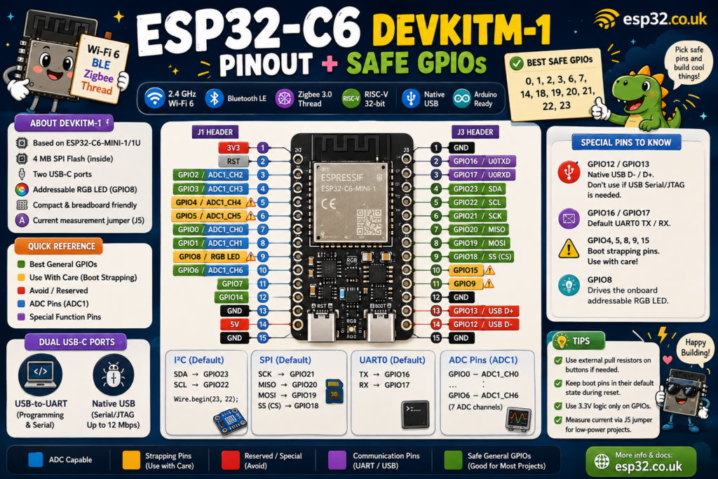
The ESP32-C6-DevKitM-1 is a compact development board based on the ESP32-C6-MINI-1 or MINI-1U, combining 2.4 GHz Wi-Fi 6, Bluetooth LE, Zigbee and Thread. For general GPIO use, good starting pins are GPIO0, 1, 2, 3, 6, 7, 14, 18, 19, 20, 21, 22 and 23. Use GPIO4, 5, 8, 9 and 15 with care because they are strapping pins. GPIO8 also drives the board’s RGB LED. GPIO12/13 are used by native USB, while GPIO16/17 are the default UART0 pins. ADC inputs are available on GPIO0 through GPIO6.
1. ESP32-C6-DevKitM-1 overview
The ESP32-C6-DevKitM-1 is Espressif’s compact C6 development board. It is built around either the ESP32-C6-MINI-1 or ESP32-C6-MINI-1U module and includes 4 MB of SPI flash inside the ESP32-C6FH4 package. The MINI-1 uses an integrated PCB antenna, while the MINI-1U uses an external antenna connector.
The board provides:
- 2.4 GHz Wi-Fi 6
- Bluetooth LE
- Zigbee 3.0
- Thread
- 32-bit RISC-V processor
- Native USB Serial/JTAG
- USB-to-UART interface
- Addressable RGB LED
- Breadboard-friendly headers
- Current-measurement jumper
Most usable GPIOs are broken out onto the two side headers.
One important difference from the larger ESP32-C6-DevKitC-1 is size. DevKitM-1 uses the smaller MINI module and exposes fewer physical header positions while still providing the GPIOs most projects need.
2. Quick safe GPIO cheat sheet
For most beginner projects, this is a useful starting point.
| GPIO group | Pins | Recommendation |
|---|---|---|
| Best general GPIOs | 0, 1, 2, 3, 6, 7, 14, 18, 19, 20, 21, 22, 23 | Good starting choices |
| ADC inputs | 0, 1, 2, 3, 4, 5, 6 | ADC1 |
| Strapping pins | 4, 5, 8, 9, 15 | Use with care |
| RGB LED | 8 | Already connected to onboard LED |
| Native USB | 12, 13 | Avoid if using USB Serial/JTAG |
| UART0 | 16, 17 | Avoid if using hardware Serial |
| Default Arduino I²C | SDA 23, SCL 22 | Recommended |
| Default Arduino SPI | SS 18, MOSI 19, MISO 20, SCK 21 | Recommended |
Espressif identifies GPIO4, GPIO5, GPIO8, GPIO9 and GPIO15 as C6 strapping pins; GPIO12/13 carry USB D−/D+, while GPIO16/17 are UART0.
3. Full ESP32-C6-DevKitM-1 pinout
The DevKitM-1 has two main headers: J1 and J3.
J1 header
| Header | Pin | Main functions |
|---|---|---|
| J1-1 | 3V3 | 3.3 V power |
| J1-2 | RST | Reset / enable |
| J1-3 | GPIO2 | GPIO, ADC1_CH2 |
| J1-4 | GPIO3 | GPIO, ADC1_CH3 |
| J1-5 | GPIO4 | GPIO, ADC1_CH4, strapping |
| J1-6 | GPIO5 | GPIO, ADC1_CH5, strapping |
| J1-7 | GPIO0 | GPIO, ADC1_CH0 |
| J1-8 | GPIO1 | GPIO, ADC1_CH1 |
| J1-9 | GPIO8 | RGB LED, strapping |
| J1-10 | GPIO6 | GPIO, ADC1_CH6 |
| J1-11 | GPIO7 | GPIO |
| J1-12 | GPIO14 | GPIO |
| J1-13 | GND | Ground |
| J1-14 | 5V | 5 V |
| J1-15 | GND | Ground |
The board documentation confirms that GPIO8 is connected to the onboard addressable RGB LED.
J3 header
| Header | Pin | Main functions |
|---|---|---|
| J3-1 | GND | Ground |
| J3-2 | GPIO16 | UART0 TX |
| J3-3 | GPIO17 | UART0 RX |
| J3-4 | GPIO23 | GPIO |
| J3-5 | GPIO22 | GPIO |
| J3-6 | GPIO21 | GPIO |
| J3-7 | GPIO20 | GPIO |
| J3-8 | GPIO19 | GPIO |
| J3-9 | GPIO18 | GPIO |
| J3-10 | GPIO15 | GPIO, strapping |
| J3-11 | GPIO9 | GPIO, strapping |
| J3-12 | GND | Ground |
| J3-13 | GPIO13 | USB D+ |
| J3-14 | GPIO12 | USB D− |
| J3-15 | GND | Ground |
These mappings come directly from Espressif’s DevKitM-1 hardware reference.
4. Best GPIOs for general use
A GPIO being physically available does not automatically mean it is the best pin for a relay, button or sensor.
For general digital input/output, a practical list is:
GPIO0, GPIO1, GPIO2, GPIO3, GPIO6, GPIO7, GPIO14, GPIO18, GPIO19, GPIO20, GPIO21, GPIO22 and GPIO23
These avoid the C6’s major boot strapping pins, native USB pair and UART0 pins.
For an especially simple project such as an LED, button or relay, good choices include:
GPIO2, GPIO3, GPIO14, GPIO18, GPIO19, GPIO20, GPIO21, GPIO22 and GPIO23
GPIO6 and GPIO7 are also usable, but they have LP-I²C/JTAG-related alternate functions, so other pins may be simpler if those features will be needed later.
5. Strapping pins: GPIO4, 5, 8, 9 and 15
The ESP32-C6 reads several GPIO states during reset to decide how the chip should boot and configure certain low-level functions.
The strapping pins are:
- GPIO4
- GPIO5
- GPIO8
- GPIO9
- GPIO15
After the reset process finishes, these pins can normally be used as GPIOs. The problem occurs when external hardware forces one of them HIGH or LOW during reset.
GPIO8 and GPIO9 are especially important
GPIO8 and GPIO9 participate in boot-mode selection.
GPIO9 has an internal weak pull-up by default. The BOOT/download circuitry therefore deserves particular attention when connecting buttons, relays or external pull resistors.
GPIO8 also controls the RGB LED
The DevKitM-1’s addressable RGB LED is connected to GPIO8. This means using GPIO8 for another peripheral can conflict with the LED.
For beginner projects, it is easier simply to choose another GPIO.
6. GPIOs to avoid or reserve
GPIO12 and GPIO13: native USB
The ESP32-C6 has an integrated USB Serial/JTAG controller.
On the DevKitM-1:
- GPIO12 = USB D−
- GPIO13 = USB D+
The board has a dedicated ESP32-C6 USB-C port connected to this interface. It can be used for flashing, communication and JTAG debugging.
If native USB is being used, leave GPIO12 and GPIO13 alone.
GPIO16 and GPIO17: UART0
The board maps:
- GPIO16 = UART0 TX
- GPIO17 = UART0 RX
These pins are useful for serial communication, but using them for unrelated outputs can interfere with UART logging or attached serial hardware.
GPIO8: RGB LED + strap
GPIO8 has two reasons to use it carefully:
- It is a strapping pin.
- It drives the onboard RGB LED.
For ordinary switches and sensors, choose another GPIO.
7. ADC pins
ESP32-C6 has one SAR ADC block exposed on several GPIOs.
On DevKitM-1 the analog-capable pins are:
| GPIO | ADC channel |
|---|---|
| GPIO0 | ADC1_CH0 |
| GPIO1 | ADC1_CH1 |
| GPIO2 | ADC1_CH2 |
| GPIO3 | ADC1_CH3 |
| GPIO4 | ADC1_CH4 |
| GPIO5 | ADC1_CH5 |
| GPIO6 | ADC1_CH6 |
Espressif therefore exposes seven ADC channels from GPIO0 through GPIO6.
For simple analog sensors, the easiest choices are:
GPIO0, GPIO1, GPIO2, GPIO3 or GPIO6
GPIO4 and GPIO5 work as ADC inputs but are strapping pins, making them less attractive for beginner projects.
ADC calibration note
Espressif states that DevKitM-1 boards produced from June 2023 onward use multi-point ADC calibration instead of the earlier two-point calibration approach.
For accurate voltage or current measurement, an external ADC such as the ADS1115 can still provide better repeatability.
8. I²C pins
Like other modern ESP32 chips, ESP32-C6 can route many peripheral signals through its GPIO matrix, so I²C is not permanently tied to one pair of pins.
For Arduino-ESP32, the standard C6 mapping is:
- GPIO23 = SDA
- GPIO22 = SCL
A second Wire interface can use:
- GPIO6 = SDA1
- GPIO7 = SCL1
Espressif’s Arduino-ESP32 board definitions use GPIO23/22 as the normal C6 I²C pair.
For sensors such as:
the easiest wiring is therefore:
| Device | ESP32-C6 |
|---|---|
| SDA | GPIO23 |
| SCL | GPIO22 |
| VCC | 3V3 |
| GND | GND |
Example Arduino setup:
#include <Wire.h>

void setup() {
  Wire.begin(23, 22);
}

void loop() {
}
9. SPI pins
The normal Arduino SPI mapping for ESP32-C6 is:
- GPIO21 = SCK
- GPIO20 = MISO
- GPIO19 = MOSI
- GPIO18 = SS / CS
These four pins are all exposed on the DevKitM-1 J3 header.
This is a convenient group for:
- TFT displays
- SD cards
- Ethernet modules
- SPI ADCs
- SPI sensors
Typical wiring:
| SPI function | GPIO |
|---|---|
| SCK | GPIO21 |
| MISO | GPIO20 |
| MOSI | GPIO19 |
| CS | GPIO18 |
Different chip-select pins can be used when several SPI devices share the same bus.
10. UART pins
UART0 is mapped to:
- TX = GPIO16
- RX = GPIO17
These pins appear directly as TX and RX on the DevKitM-1 header.
They are useful for:
- GPS receivers
- RS-485 converters
- particulate sensors such as PMS5003
- serial displays
- other microcontrollers
Remember that TX and RX must normally be crossed:
ESP32 TX → device RX
ESP32 RX ← device TX
11. RGB LED
The DevKitM-1 includes an addressable RGB LED connected to GPIO8.
Because this is an addressable LED rather than a simple single-colour LED, traditional code such as:
digitalWrite(8, HIGH);
does not produce normal RGB control.
Use an addressable-LED library or the Arduino ESP32 RGB LED helpers supported by the installed core.
Also remember that GPIO8 is a strapping pin, so it should not be treated as a completely unrestricted GPIO.
12. USB ports
One useful feature of the DevKitM-1 is that it has two USB-C interfaces.
USB-to-UART port
This port connects through an onboard USB-to-UART bridge and can be used for:
- powering the board
- flashing firmware
- Serial communication
Native ESP32-C6 USB port
The second USB-C connector goes directly to the C6’s USB Serial/JTAG interface.
It supports USB 2.0 full-speed operation up to 12 Mbps and can be used for:
- power
- flashing
- serial communication
- JTAG debugging
GPIO12 and GPIO13 belong to this interface.
13. Power pins
The board exposes:
- 3V3
- 5V
- multiple GND pins
Espressif supports three power arrangements:
- USB-C
- 5V + GND header
- 3V3 + GND header
USB power is the normal development method.
The board also includes a 5 V-to-3.3 V LDO for powering the ESP32-C6 module.
Remember that GPIO logic is 3.3 V. Do not feed 5 V directly into a GPIO.
14. Current measurement jumper
The J5 jumper is included specifically for measuring the current consumed by the ESP32-C6 module.
Removing the jumper disconnects the module’s normal power path so an ammeter can be connected through J5. Reinstalling the jumper restores normal operation.
This makes DevKitM-1 particularly useful for experimenting with:
- deep sleep
- battery-powered sensors
- Wi-Fi power consumption
- Thread/Zigbee power consumption
- optimisation of wake intervals
15. Recommended GPIO recipes
I²C environmental sensor
| Function | GPIO |
|---|---|
| SDA | GPIO23 |
| SCL | GPIO22 |
SPI display
| Function | GPIO |
|---|---|
| SCK | GPIO21 |
| MISO | GPIO20 |
| MOSI | GPIO19 |
| CS | GPIO18 |
Analog sensor
Use:
GPIO0, GPIO1, GPIO2, GPIO3 or GPIO6
These provide ADC capability without choosing GPIO4 or GPIO5 strapping pins.
Relay
Good starting options:
GPIO14, GPIO18, GPIO19 or GPIO20
Avoid GPIO8 for a relay because it is both a strapping pin and connected to the RGB LED.
Pushbutton
A simple choice is:
GPIO2 or GPIO3
Use:
pinMode(2, INPUT_PULLUP);
and connect the button between GPIO2 and GND.
16. ESP32-C6 pin capability table
| GPIO | Digital I/O | ADC | Special use | Recommendation |
|---|---|---|---|---|
| 0 | Yes | ADC1_CH0 | LP GPIO | ✅ Good |
| 1 | Yes | ADC1_CH1 | LP GPIO | ✅ Good |
| 2 | Yes | ADC1_CH2 | LP GPIO | ✅ Good |
| 3 | Yes | ADC1_CH3 | LP GPIO | ✅ Good |
| 4 | Yes | ADC1_CH4 | Strapping / JTAG | ⚠️ Care |
| 5 | Yes | ADC1_CH5 | Strapping / JTAG | ⚠️ Care |
| 6 | Yes | ADC1_CH6 | JTAG / alternate I²C | ✅ Usually good |
| 7 | Yes | No | JTAG / alternate I²C | ✅ Usually good |
| 8 | Yes | No | Strap + RGB LED | ⚠️ Avoid for general use |
| 9 | Yes | No | Strapping | ⚠️ Care |
| 12 | Yes | No | USB D− | ⚠️ Reserve for USB |
| 13 | Yes | No | USB D+ | ⚠️ Reserve for USB |
| 14 | Yes | No | General GPIO | ✅ Excellent |
| 15 | Yes | No | Strapping | ⚠️ Care |
| 16 | Yes | No | UART0 TX | ⚠️ Serial use |
| 17 | Yes | No | UART0 RX | ⚠️ Serial use |
| 18 | Yes | No | SPI SS | ✅ Good |
| 19 | Yes | No | SPI MOSI | ✅ Good |
| 20 | Yes | No | SPI MISO | ✅ Good |
| 21 | Yes | No | SPI SCK | ✅ Good |
| 22 | Yes | No | I²C SCL | ✅ Good |
| 23 | Yes | No | I²C SDA | ✅ Good |
The DevKitM-1 does not break GPIO10 or GPIO11 out to its headers, despite those GPIO numbers existing on other C6 board configurations.
17. Pins beginners should remember
If only a few rules are remembered, make them these:
Best general GPIOs:
GPIO0, 1, 2, 3, 6, 7, 14, 18, 19, 20, 21, 22, 23
ADC:
GPIO0–6
I²C:
GPIO23 SDA, GPIO22 SCL
SPI:
GPIO21 SCK, GPIO20 MISO, GPIO19 MOSI, GPIO18 CS
UART:
GPIO16 TX, GPIO17 RX
Native USB:
GPIO12 and GPIO13
Use carefully:
GPIO4, 5, 8, 9, 15
RGB LED:
GPIO8
Those few rules prevent most pin-selection problems on ESP32-C6-DevKitM-1.
18. ESP32-C6-DevKitM-1 vs DevKitC-1
Both boards use the same ESP32-C6 family and provide Wi-Fi 6, BLE and 802.15.4.
The major difference is physical design.
DevKitM-1 uses the compact MINI module and a smaller 15-pin-per-side layout.
DevKitC-1 uses the larger WROOM module and a larger header layout.
DevKitM-1 is therefore attractive for compact prototypes, while DevKitC-1 provides more board space and a more traditional full-size development-board layout.
19. Final recommendation
For most ESP32-C6-DevKitM-1 projects, begin with:
- GPIO23/22 for I²C
- GPIO18–21 for SPI
- GPIO0–3 or GPIO6 for analog
- GPIO14 for a simple relay, LED or digital output
- GPIO16/17 for UART
Leave GPIO12/13 available if native USB is needed, and avoid attaching hardware that forces GPIO4, GPIO5, GPIO8, GPIO9 or GPIO15 to an unwanted level during reset.
That approach gives plenty of GPIO flexibility while avoiding nearly all of the board’s common boot and peripheral conflicts.