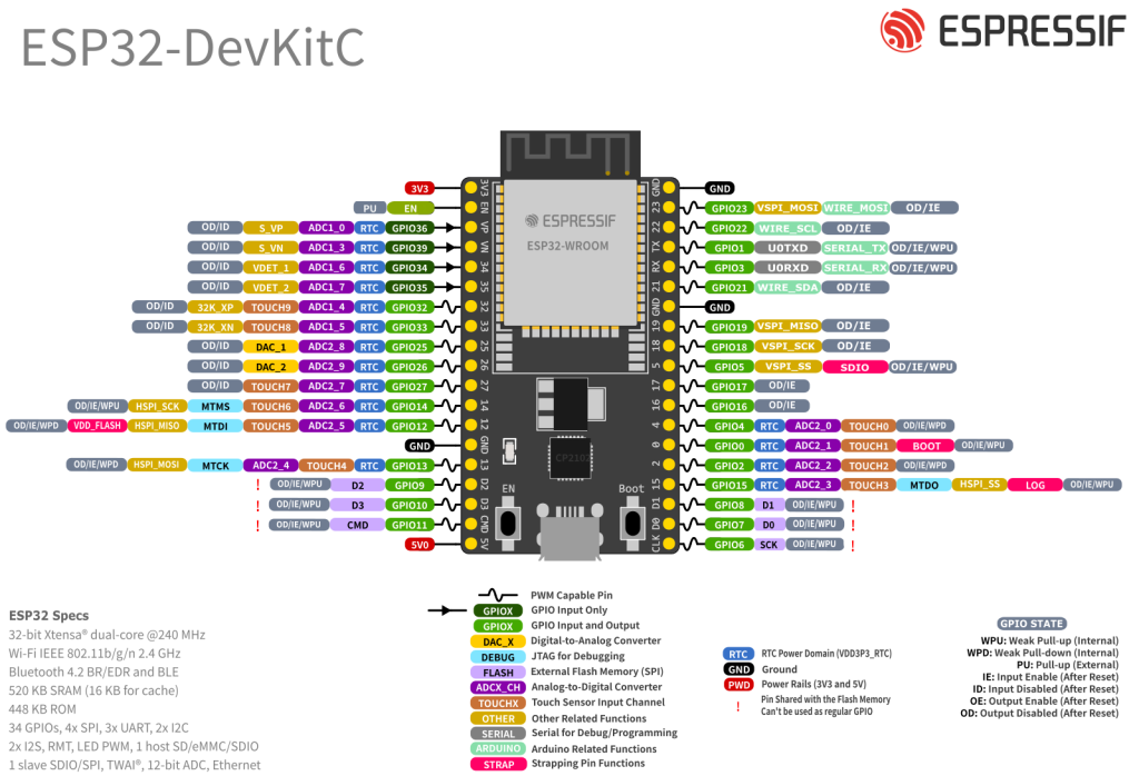
1. ESP32 DevKit / ESP-WROOM-32 Overview
The ESP32-WROOM-32 module exposes up to 32 GPIO pins, plus power, enable and boot configuration pins. These GPIOs are highly multiplexed: the same pin can often be used as digital I/O, ADC, touch, I²C, SPI, UART, PWM etc.
Key ideas before touching any pin:
- Logic level is 3.3 V only – higher voltages (like 5 V) can damage the chip.
- Some pins are input-only.
- Some pins are strapping/boot pins – their level at reset decides boot mode.
- Some pins are permanently used for on-board SPI flash and should be avoided.
2. Quick “safe pins” cheat sheet
For a typical ESP32 DevKit v1 / WROOM-32 board, the following is a good mental model:
| GPIO Pin | Function | Status | Note |
| 34, 35, 36, 39 | Input Only | ✅ Safe | No pull-ups; Input only |
| 32, 33 | Analog/Digital | ✅ Safe | Great for ADC (Wi-Fi safe) |
| 25, 26, 27 | Digital I/O | ✅ Safe | Good for Relays/LEDs |
| 16, 17, 18, 19 | SPI / UART | ✅ Safe | Good for sensors/displays |
| 21, 22 | I2C | ✅ Safe | Default SDA/SCL |
| 1, 3 | TX / RX | ⚠️ Risky | Connected to USB/Serial |
| 0, 2, 5, 12, 15 | Strapping | ⚠️ Risky | Affects Boot Mode (High/Low) |
| 6, 7, 8, 9, 10, 11 | SPI Flash | ❌ Unsafe | Do not use (Crash) |
2.1 Best general-purpose GPIOs (digital input/output, PWM, etc.)
These are usually trouble-free and recommended for most projects:
- GPIOs 13, 14, 16, 17, 18, 19, 21, 22, 23, 25, 26, 27, 32, 33
They support digital I/O, PWM, many peripheral functions and don’t normally interfere with boot or flash.
2.2 GPIOs to use with care
These work, but have special roles:
- Strapping / boot pins: GPIO0, 2, 4, 5, 12, 15
Their level during reset decides if the ESP32 boots normally or enters programming modes. - USB-Serial / programming pins: GPIO1 (TX0), GPIO3 (RX0)
Used by the onboard USB-UART for flashing and Serial Monitor.
Using these for buttons, relays, pull-downs, etc. is possible, but bad wiring can:
- Prevent boot
- Lock the chip in flashing mode
- Hide boot messages
2.3 Pins to avoid on DevKits
- GPIO6, 7, 8, 9, 10, 11 – connected internally to the SPI flash. Don’t use them.
3. Input-only GPIOs (perfect for sensors, not for outputs)
The ESP32 has a group of pins that are input-only and lack internal pull-ups/pull-downs:
- GPIO34, GPIO35, GPIO36 (VP), GPIO39 (VN)
Characteristics:
- Can be used as digital inputs or ADC inputs (ADC1)
- Cannot drive outputs (no output driver)
- No internal pull-ups/pull-downs → use external resistors if needed
These are excellent for:
- Buttons (with external pull-up/down)
- Analog sensors (e.g. voltage dividers, potentiometers)
- “Input only” logic signals from other boards
4. Strapping (boot) pins – what not to do
Strapping pins are read at reset to choose boot mode, flash voltage, etc.
- GPIO0 – must be HIGH to boot normally, LOW to enter flashing mode
- GPIO2 – used in boot mode selection, default pull-down
- GPIO5 – influences SDIO timing
- GPIO12 (MTDI) – affects flash voltage; pulling it HIGH at boot can prevent start-up
- GPIO15 (MTDO) – must be HIGH for normal boot; LOW can suppress boot logs
Practical rule:
If these pins are used in a project, avoid hard pull-downs or heavy loads that may force them LOW/HIGH at reset.
5. Power pins & EN
Typical DevKit power pins:
- 3V3 – regulated 3.3 V output from the on-board regulator (or input, for bare modules).
- VIN / 5V – USB 5 V input (and often available as a pin to power small external circuits).
- GND – ground.
- EN – chip enable; HIGH = run, LOW = reset/disable.
On most DevKits you feed 5 V to VIN or via USB, and use the onboard 3.3 V for sensors. For external loads, keep current reasonable – the tiny regulator is not a bench supply.
6. ADC pins (analog inputs)
The ESP32 has two ADC blocks: ADC1 and ADC2, with up to 18 analog channels and up to 12-bit resolution.
6.1 ADC1 vs ADC2
On ESP-WROOM-32:
- ADC1 channels (safe with Wi-Fi) – on GPIO 32, 33, 34, 35, 36, 39
- ADC2 channels – on GPIO 0, 2, 4, 12, 13, 14, 15, 25, 26, 27 (availability depends on board)
Critical limitation:
When Wi-Fi is enabled, ADC2 pins cannot be used reliably. Only ADC1 remains usable.
So for typical Wi-Fi projects (MQTT, web servers, Home Assistant, etc.):
- Prefer ADC inputs on GPIO32, 33, 34, 35, 36, 39.
6.2 ADC basics
- Voltage range: approximately 0–3.3 V. Higher voltages require a resistor divider.
- Resolution: up to 12 bits → 4096 steps (~0.8 mV per step at 3.3 V).
7. Capacitive touch pins
ESP32 includes 10 capacitive touch GPIOs (TOUCH0–TOUCH9) that detect finger proximity and can even wake the ESP32 from deep sleep.
On ESP-WROOM-32 these map roughly to:
- TOUCH0 → GPIO4
- TOUCH1 → GPIO0
- TOUCH2 → GPIO2
- TOUCH3 → GPIO15
- TOUCH4 → GPIO13
- TOUCH5 → GPIO12
- TOUCH6 → GPIO14
- TOUCH7 → GPIO27
- TOUCH8 → GPIO33
- TOUCH9 → GPIO32
Usage notes:
- Read via
touchRead(GPIO)in Arduino IDE. - Can be configured as wake-up sources from deep sleep.
- Many touch pins overlap with strapping pins → design carefully.
8. I²C pins (SDA / SCL)
The ESP32 has flexible I²C routing – any GPIO can be used as SDA/SCL. However, most examples and libraries assume the default pair:
- GPIO21 → SDA
- GPIO22 → SCL
This convention is worth following unless there is a very good reason not to, especially for compatibility with libraries and tutorials.
Example Arduino setup:
Wire.begin(21, 22); // SDA, SCL
9. SPI pins
The ESP32 exposes three SPI controllers: SPI, HSPI, VSPI. One is used internally for the SPI flash (on GPIO6–11), the other two are free for user devices.
Like I²C, SPI pins are configurable, but typical DevKit defaults for VSPI are:
- GPIO18 → SCK
- GPIO19 → MISO
- GPIO23 → MOSI
- GPIO5 → CS (chip select)
These are safe, high-speed pins and work well for:
- Displays (SPI TFT, OLED)
- External ADC/DAC
- SD cards (if not using an ESP32-CAM style module)
Avoid GPIO6–11 – they are connected to the on-board flash.
10. UART / Serial pins
The ESP32 has three UARTs: UART0, UART1, UART2.
Typical mapping on DevKit:
- UART0 – main serial / flashing
- TX0 → GPIO1, RX0 → GPIO3
- UART2 – common extra serial port
- Often mapped to GPIO17 (TX2) and GPIO16 (RX2)
UART1 is internally tied to flash pins on many WROOM modules, so it’s usually ignored or remapped.
For projects needing hardware Serial for another device (GPS, RS-485, etc.), UART2 on GPIO16/17 is usually the cleanest choice.
11. Practical pin recipes
11.1 Simple sensor + relay node
A safe, re-usable pattern for a classic “sensor + relay” node:
| Function | Recommended GPIOs | Notes |
|---|---|---|
| I²C SDA | GPIO21 | BME280, OLED, etc. |
| I²C SCL | GPIO22 | |
| Relay / digital out | GPIO25 / GPIO26 / GPIO27 | Avoid boot pins if relay pulls heavy current at reset |
| Extra digital input | GPIO32 / GPIO33 | Can also be ADC1 |
| Analog sensor input | GPIO34 / 35 / 36 / 39 | Input-only ADC1 (Wi-Fi-safe) |
11.2 Touch button that wakes the ESP32
| Function | Recommended GPIOs | Notes |
|---|---|---|
| Touch button | GPIO33 or GPIO32 | TOUCH8 / TOUCH9, not strapping pins |
| Wake from sleep | same pin | Configure as touch wake source |
12. Summary – “safe pin” rules of thumb
For classic ESP32 DevKit / ESP-WROOM-32 boards:
- Digital I/O / PWM
→ Start with 13, 14, 16, 17, 18, 19, 21, 22, 23, 25, 26, 27, 32, 33. - Analog inputs with Wi-Fi enabled
→ Use ADC1: 32, 33, 34, 35, 36, 39. - I²C bus
→ Use 21 (SDA) and 22 (SCL) unless there’s a strong reason not to. - SPI devices
→ Use 18 (SCK), 19 (MISO), 23 (MOSI), 5 (CS). - Avoid
→ 6–11 (flash), and heavy loads on 0, 2, 4, 5, 12, 15 at boot. - Remember
→ 34–39 are input-only and have no internal pull-ups.