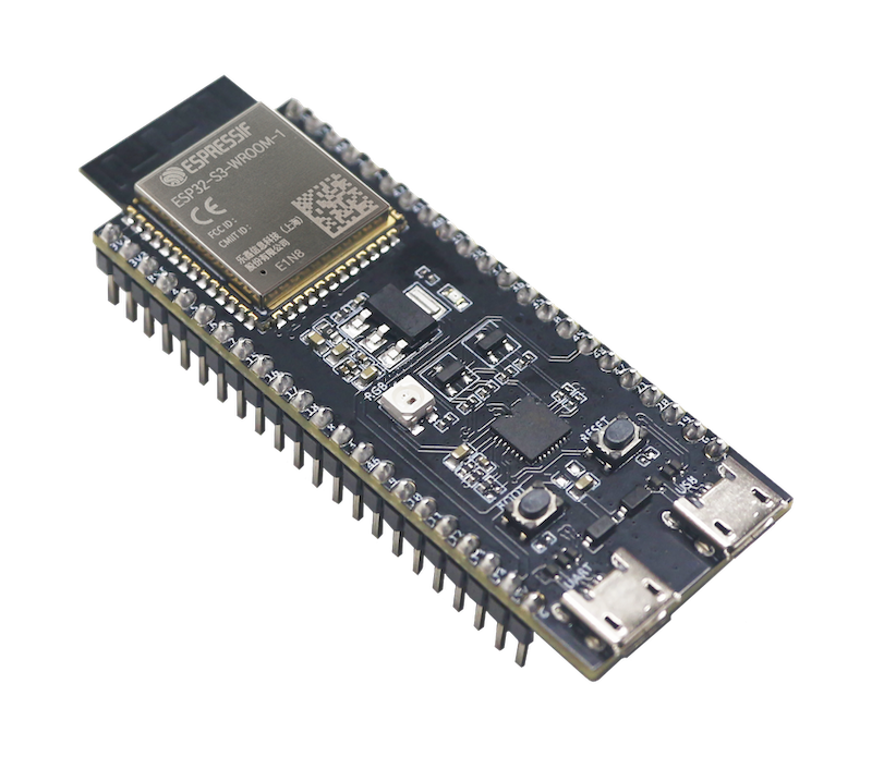
The ESP32-S3-DevKitC-1AliExpress price has a lot of GPIOs, but not every pin is equally convenient to use.
Some pins affect boot, some are shared with native USB or debugging, and GPIO35–37 may be unavailable depending on the flash and PSRAM configuration of the module fitted to your board.
This guide focuses on ESP32-S3-DevKitC-1AliExpress price pinout and GPIO selection, so you can connect sensors, relays, displays, SPI devices, UART peripherals and USB hardware without unexpected boot or peripheral conflicts.
The ESP32-S3-DevKitC-1AliExpress price is Espressif’s official entry-level development board for ESP32-S3AliExpress price-WROOM-1, ESP32-S3AliExpress price-WROOM-1U and ESP32-S3-WROOM-2 modules.
The ESP32-S3 combines a dual-core Xtensa LX7 processor with 2.4 GHz Wi-Fi, Bluetooth Low Energy, native USB and a flexible GPIO matrix.
Scope: This guide covers the official ESP32-S3-DevKitC-1 with the J1 and J3 22-pin headers. The board exists in several flash/PSRAM configurations and in more than one hardware revision, which matters for a few GPIOs.
You can compare your board with the official ESP32-S3-DevKitC-1 documentation.
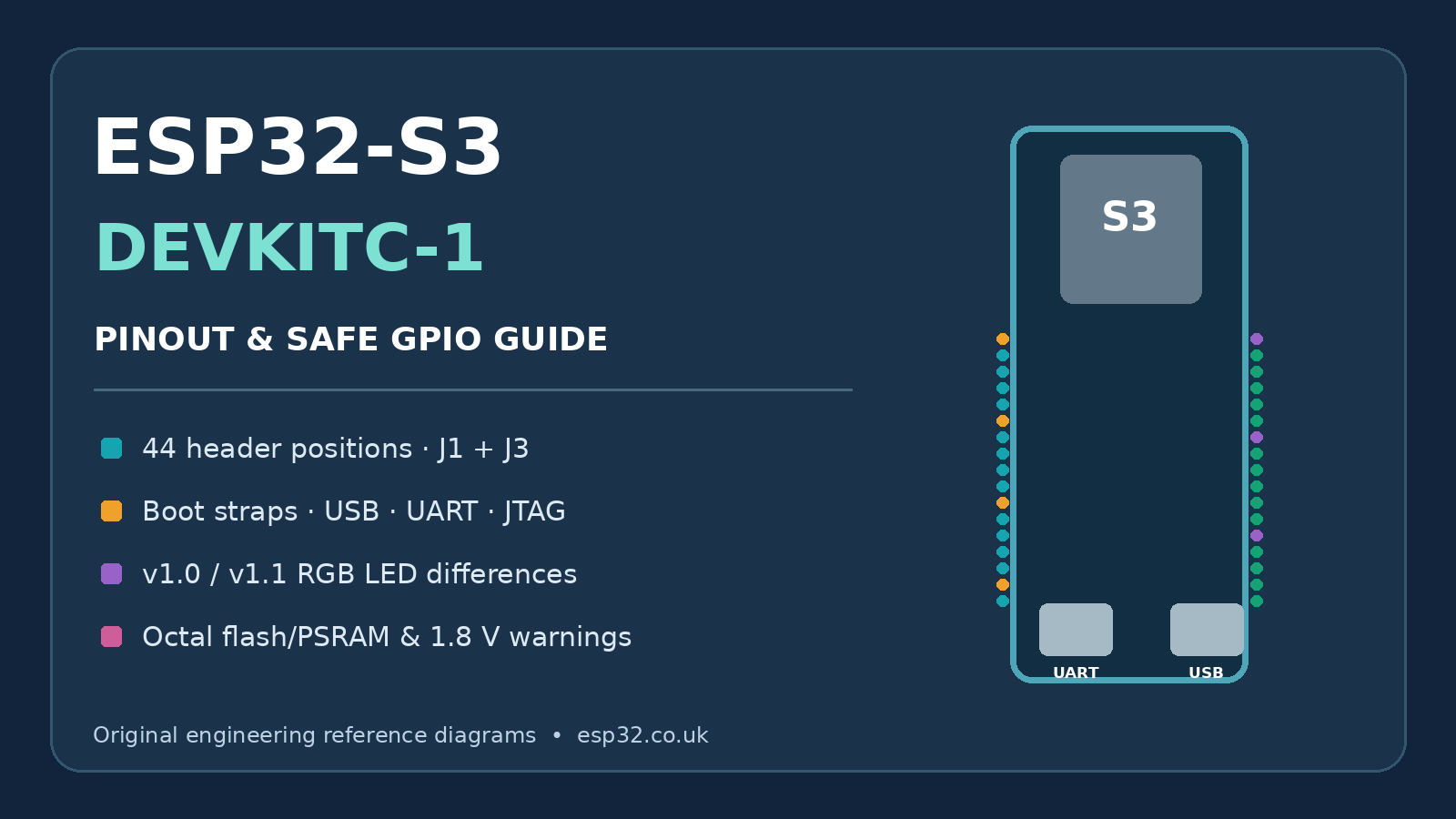
ESP32-S3 DevKitC-1 GPIO Quick Reference
If you simply want to know which pins to use, start here.
| GPIO group | Recommendation |
|---|---|
| GPIO1, 2, 4–18 and 21 | Best general-purpose starting points |
| GPIO0, 3, 45, 46 | Avoid for normal peripherals: strapping pins |
| GPIO19, 20 | Reserve when using native USB |
| GPIO35, 36, 37 | Module-dependent: unavailable on several Octal-memory versions |
| GPIO38 | RGB LED on DevKitC-1 v1.1 |
| GPIO48 | RGB LED on the original DevKitC-1 |
| GPIO39–42 | Usable, but also associated with external JTAG |
| GPIO43, 44 | UART0 / USB-to-UART console |
| GPIO26–32 | Internal flash/PSRAM bus; not broken out for normal use |
For a project that needs ordinary digital inputs and outputs, GPIO1, GPIO2, GPIO4–18 and GPIO21 are the lowest-drama group to start with.
J1
| No. | Name | Type 1 | Function |
|---|---|---|---|
| 1 | 3V3 | P | 3.3 V power supply |
| 2 | 3V3 | P | 3.3 V power supply |
| 3 | RST | I | EN |
| 4 | 4 | I/O/T | RTC_GPIO4, GPIO4, TOUCH4, ADC1_CH3 |
| 5 | 5 | I/O/T | RTC_GPIO5, GPIO5, TOUCH5, ADC1_CH4 |
| 6 | 6 | I/O/T | RTC_GPIO6, GPIO6, TOUCH6, ADC1_CH5 |
| 7 | 7 | I/O/T | RTC_GPIO7, GPIO7, TOUCH7, ADC1_CH6 |
| 8 | 15 | I/O/T | RTC_GPIO15, GPIO15, U0RTS, ADC2_CH4, XTAL_32K_P |
| 9 | 16 | I/O/T | RTC_GPIO16, GPIO16, U0CTS, ADC2_CH5, XTAL_32K_N |
| 10 | 17 | I/O/T | RTC_GPIO17, GPIO17, U1TXD, ADC2_CH6 |
| 11 | 18 | I/O/T | RTC_GPIO18, GPIO18, U1RXD, ADC2_CH7, CLK_OUT3 |
| 12 | 8 | I/O/T | RTC_GPIO8, GPIO8, TOUCH8, ADC1_CH7, SUBSPICS1 |
| 13 | 3 | I/O/T | RTC_GPIO3, GPIO3, TOUCH3, ADC1_CH2 |
| 14 | 46 | I/O/T | GPIO46 |
| 15 | 9 | I/O/T | RTC_GPIO9, GPIO9, TOUCH9, ADC1_CH8, FSPIHD, SUBSPIHD |
| 16 | 10 | I/O/T | RTC_GPIO10, GPIO10, TOUCH10, ADC1_CH9, FSPICS0, FSPIIO4, SUBSPICS0 |
| 17 | 11 | I/O/T | RTC_GPIO11, GPIO11, TOUCH11, ADC2_CH0, FSPID, FSPIIO5, SUBSPID |
| 18 | 12 | I/O/T | RTC_GPIO12, GPIO12, TOUCH12, ADC2_CH1, FSPICLK, FSPIIO6, SUBSPICLK |
| 19 | 13 | I/O/T | RTC_GPIO13, GPIO13, TOUCH13, ADC2_CH2, FSPIQ, FSPIIO7, SUBSPIQ |
| 20 | 14 | I/O/T | RTC_GPIO14, GPIO14, TOUCH14, ADC2_CH3, FSPIWP, FSPIDQS, SUBSPIWP |
| 21 | 5V | P | 5 V power supply |
| 22 | G | G | Ground |
J3
| No. | Name | Type | Function |
|---|---|---|---|
| 1 | G | G | Ground |
| 2 | TX | I/O/T | U0TXD, GPIO43, CLK_OUT1 |
| 3 | RX | I/O/T | U0RXD, GPIO44, CLK_OUT2 |
| 4 | 1 | I/O/T | RTC_GPIO1, GPIO1, TOUCH1, ADC1_CH0 |
| 5 | 2 | I/O/T | RTC_GPIO2, GPIO2, TOUCH2, ADC1_CH1 |
| 6 | 42 | I/O/T | MTMS, GPIO42 |
| 7 | 41 | I/O/T | MTDI, GPIO41, CLK_OUT1 |
| 8 | 40 | I/O/T | MTDO, GPIO40, CLK_OUT2 |
| 9 | 39 | I/O/T | MTCK, GPIO39, CLK_OUT3, SUBSPICS1 |
| 10 | 38 | I/O/T | GPIO38, FSPIWP, SUBSPIWP, RGB LED |
| 11 | 37 | I/O/T | SPIDQS, GPIO37, FSPIQ, SUBSPIQ |
| 12 | 36 | I/O/T | SPIIO7, GPIO36, FSPICLK, SUBSPICLK |
| 13 | 35 | I/O/T | SPIIO6, GPIO35, FSPID, SUBSPID |
| 14 | 0 | I/O/T | RTC_GPIO0, GPIO0 |
| 15 | 45 | I/O/T | GPIO45 |
| 16 | 48 | I/O/T | GPIO48, SPICLK_N, SUBSPICLK_N_DIFF |
| 17 | 47 | I/O/T | GPIO47, SPICLK_P, SUBSPICLK_P_DIFF |
| 18 | 21 | I/O/T | RTC_GPIO21, GPIO21 |
| 19 | 20 | I/O/T | RTC_GPIO20, GPIO20, U1CTS, ADC2_CH9, CLK_OUT1, USB_D+ |
| 20 | 19 | I/O/T | RTC_GPIO19, GPIO19, U1RTS, ADC2_CH8, CLK_OUT2, USB_D- |
| 21 | G | G | Ground |
| 22 | G | G | Ground |
P: Power supply; I: Input; O: Output; T: High impedance.
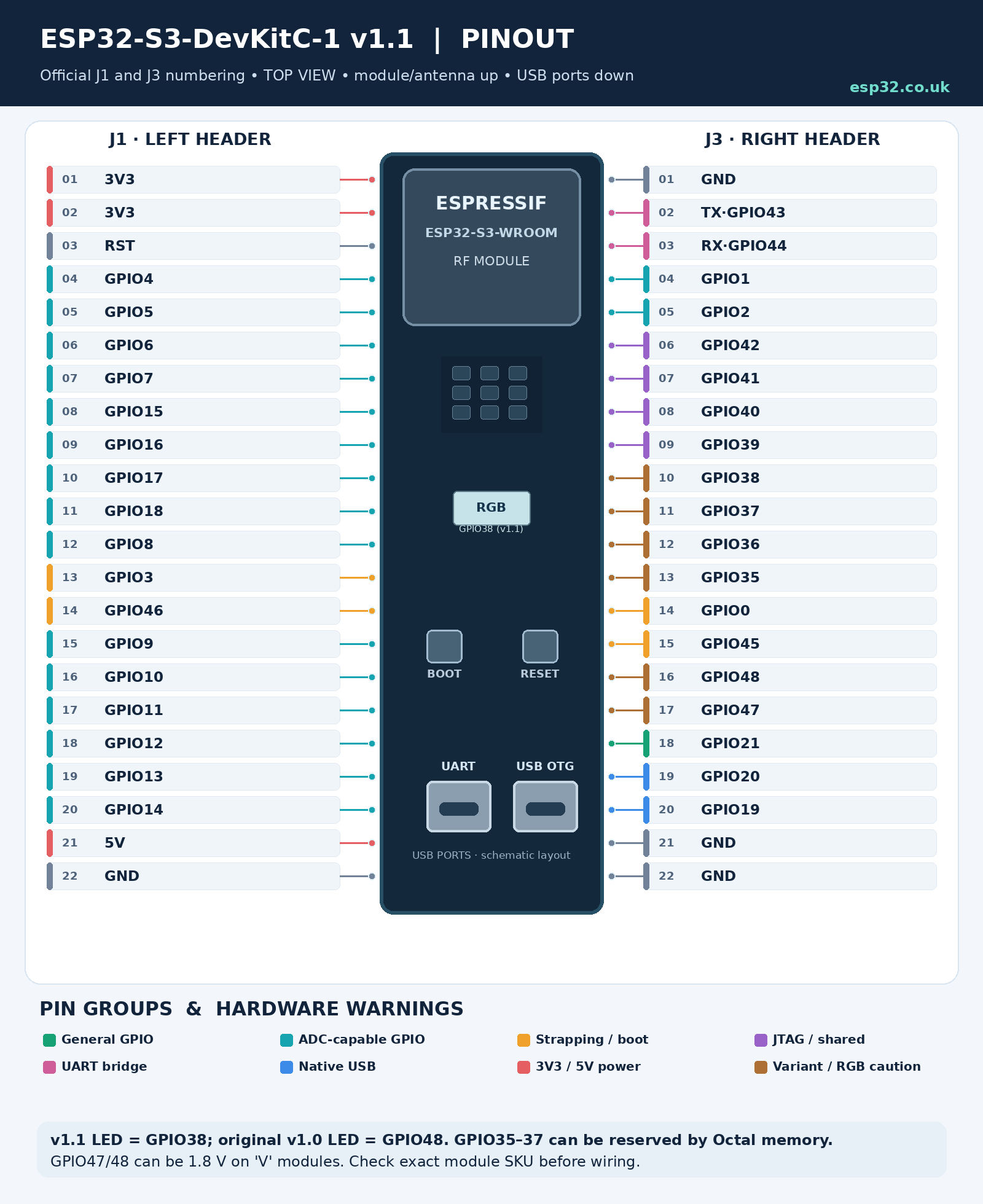
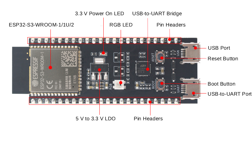
Board Overview
The ESP32-S3-DevKitC-1 exposes most usable ESP32-S3 signals through two 22-pin headers labelled J1 and J3.
The board includes:
- ESP32-S3-WROOM-1, WROOM-1U or WROOM-2 module
- 5 V to 3.3 V regulator
- USB-to-UART programming port
- native ESP32-S3 USB port
- BOOT button
- RESET / EN button
- addressable RGB LED
- 3.3 V power LED
- two 22-pin headers
The USB-to-UART port provides the traditional serial programming interface.
The second USB connector is connected directly to the ESP32-S3’s native USB peripheral and can be used for USB devices, USB host applications, firmware upload and built-in USB JTAG.
Watch the RGB LED pin
There are two DevKitC-1 hardware revisions still in circulation.
Original ESP32-S3-DevKitC-1:
- RGB LED → GPIO48
ESP32-S3-DevKitC-1 v1.1:
- RGB LED → GPIO38
So don’t blindly assume GPIO48 controls the LED just because an older tutorial says so.
If you don’t know which revision you have, treat both GPIO38 and GPIO48 as potentially board-connected until you identify it.
Power Supply Options
There are three basic ways to power the DevKitC-1:
- through the USB ports
- through 5V + GND
- through 3V3 + GND
The USB-to-UART and native USB ports form the normal USB power option; Espressif allows either USB connector, or both, to be connected.
For normal development, the easiest option is simply to use the USB-to-UART connector.
If you’re powering the board from another system:
5V pin
Feed the board with a stable 5 V supply and let its onboard regulator generate 3.3 V.
This is a good option when powering an ESP32 project from something such as a 12 V supply through a DC/DC converter.
3V3 pin
You can bypass the onboard regulator and feed regulated 3.3 V directly.
Your external supply needs enough transient capability for Wi-Fi activity and any peripherals connected to the board.
ESP32-S3 GPIOs are 3.3 V logic
Do not connect 5 V signals directly to an ESP32-S3 GPIO.
Use a level shifter, resistor divider or suitable interface circuit when connecting 5 V hardware.
ESP32-S3 GPIO Basics
The ESP32-S3 has 45 physical GPIOs:
GPIO0–21 and GPIO26–48
GPIO22–25 do not exist.
The important word here is physical. Not every chip GPIO is actually available on the DevKitC-1 headers.
The DevKitC-1 breaks out the GPIOs that remain available after the module’s flash/PSRAM connections are taken into account.
ESP32-S3 GPIOs are highly multiplexed. Through the GPIO matrix, peripherals such as I²C, SPI, UART, PWM and I²S can be routed to many different pins instead of being permanently tied to one fixed pinout.
That flexibility is one of the S3’s biggest advantages, but it also means a pin marked with one peripheral function can often be used for something completely different.
Strapping Pins: GPIO0, GPIO3, GPIO45 and GPIO46
The ESP32-S3 has four strapping pins:
- GPIO0
- GPIO3
- GPIO45
- GPIO46
Their logic levels are sampled during reset and can affect how the chip starts.
Their functions include:
| GPIO | Boot-time function |
|---|---|
| GPIO0 | Boot mode |
| GPIO46 | Boot mode and ROM output behaviour |
| GPIO45 | VDD_SPI configuration |
| GPIO3 | JTAG source selection |
GPIO0 is the one most users encounter because pulling it LOW while resetting the ESP32-S3 enters download mode.
That’s exactly what the BOOT button does.
After boot, these pins can operate as GPIOs, but attaching external circuitry that holds one of them at the wrong level during reset can produce confusing startup problems.
Recommendation
Unless you’re short of pins, leave GPIO0, GPIO3, GPIO45 and GPIO46 out of ordinary sensor, relay and display wiring.
There are enough easier GPIOs on the S3 that using strapping pins usually isn’t worth the trouble.
Safe GPIOs for Everyday Projects
For a project that must work across the common DevKitC-1 variants, a useful default GPIO pool is:
GPIO1, GPIO2, GPIO4–18 and GPIO21
These avoid:
- the four strapping pins
- native USB
- the module-dependent GPIO35–37 group
- the onboard RGB LED on either board revision
- UART0
- the traditional external JTAG pins
That doesn’t mean all the other GPIOs are unusable.
It simply means these pins generally require the least thought.
GPIOs that are usable with conditions
GPIO19 and GPIO20
Perfectly usable as GPIO or ADC inputs if you are not using native USB.
If native USB is active, reserve them for USB.
GPIO35, GPIO36 and GPIO37
Whether these pins are available depends on the module fitted to your DevKitC-1.
On boards using ESP32-S3-WROOM modules with certain Octal flash/PSRAM configurations, GPIO35–37 are used internally and cannot be used externally.
If you are writing a guide or designing something intended to work with multiple DevKitC-1 versions, don’t depend on GPIO35–37.
Additional caution for GPIO47 and GPIO48: Espressif documents that these GPIOs operate at 1.8 V on ESP32-S3-WROOM-2 modules built with ESP32-S3R8V or ESP32-S3R16V. They must not be treated as universal 3.3 V outputs or inputs. On original DevKitC-1 boards, GPIO48 also drives the RGB LED; on v1.1, that LED moved to GPIO38. For portable projects, prefer GPIO1, GPIO2, GPIO4–18 and GPIO21.
GPIO38 and GPIO48
One of these drives the addressable RGB LED depending on the board revision.
They can still be useful when you know exactly which DevKitC-1 revision you have.
GPIO39–42
These pins can be GPIOs, but they are also the traditional JTAG signals:
- GPIO39 → MTCK
- GPIO40 → MTDO
- GPIO41 → MTDI
- GPIO42 → MTMS
If you don’t use external JTAG debugging, they become useful additional GPIOs.
GPIO43 and GPIO44
These are the default UART0 console signals:
- GPIO43 → TX0
- GPIO44 → RX0
They are connected to the board’s USB-to-UART interface.
You can repurpose them, but doing so can interfere with serial logging, programming workflows or anything connected through the USB-to-UART bridge.
ADC Pins
The ESP32-S3 has two 12-bit SAR ADC units providing 20 analog channels.
ADC1
ADC1 uses GPIO1–10:
| GPIO | ADC channel |
|---|---|
| GPIO1 | ADC1_CH0 |
| GPIO2 | ADC1_CH1 |
| GPIO3 | ADC1_CH2 |
| GPIO4 | ADC1_CH3 |
| GPIO5 | ADC1_CH4 |
| GPIO6 | ADC1_CH5 |
| GPIO7 | ADC1_CH6 |
| GPIO8 | ADC1_CH7 |
| GPIO9 | ADC1_CH8 |
| GPIO10 | ADC1_CH9 |
GPIO3 is also a strapping pin, so I would normally use GPIO1, GPIO2 or GPIO4–10 first.
ADC2
ADC2 uses GPIO11–20:
| GPIO | ADC channel |
|---|---|
| GPIO11 | ADC2_CH0 |
| GPIO12 | ADC2_CH1 |
| GPIO13 | ADC2_CH2 |
| GPIO14 | ADC2_CH3 |
| GPIO15 | ADC2_CH4 |
| GPIO16 | ADC2_CH5 |
| GPIO17 | ADC2_CH6 |
| GPIO18 | ADC2_CH7 |
| GPIO19 | ADC2_CH8 |
| GPIO20 | ADC2_CH9 |
ADC2 is shared with the Wi-Fi subsystem.
Current ESP-IDF handles ADC2 oneshot access better than older ESP32 software did, but ADC2 remains more constrained when Wi-Fi is active, and ADC2 continuous-mode sampling is not recommended on the ESP32-S3.
Best practical choice for analog sensors
For a normal Wi-Fi project, use ADC1 on GPIO1–10 where possible.
My first choices would be:
GPIO1, GPIO2, GPIO4, GPIO5, GPIO6 or GPIO7
GPIO8–10 are also excellent, although you may want to reserve GPIO8/9 for I²C and GPIO10 for SPI chip select if you follow the mappings later in this guide.
Never allow the analog input to exceed the ESP32-S3’s 3.3 V supply domain.
For accurate voltage measurements, also remember that an ESP32 ADC is not a laboratory ADC: use calibration if accuracy matters.
Capacitive Touch Pins
The ESP32-S3 has 14 capacitive touch channels on GPIO1–14.
| GPIO | Touch channel |
|---|---|
| GPIO1 | TOUCH1 |
| GPIO2 | TOUCH2 |
| GPIO3 | TOUCH3 |
| GPIO4 | TOUCH4 |
| GPIO5 | TOUCH5 |
| GPIO6 | TOUCH6 |
| GPIO7 | TOUCH7 |
| GPIO8 | TOUCH8 |
| GPIO9 | TOUCH9 |
| GPIO10 | TOUCH10 |
| GPIO11 | TOUCH11 |
| GPIO12 | TOUCH12 |
| GPIO13 | TOUCH13 |
| GPIO14 | TOUCH14 |
For a straightforward touch input, I would avoid the GPIO3 strapping pin and start with:
GPIO4–14
Touch inputs can also be used as wake-up sources in low-power projects.
Native USB Pins
Unlike the original ESP32, the ESP32-S3 includes native full-speed USB OTG.
The USB data pins are fixed:
- GPIO19 → USB D-
- GPIO20 → USB D+
These lines are connected to the ESP32-S3 USB connector on the DevKitC-1.
If you’re using native USB for something such as:
- USB CDC serial
- HID keyboard or mouse
- MIDI
- USB storage
- USB host
- USB Serial/JTAG
treat GPIO19 and GPIO20 as reserved USB pins.
Do not attach ordinary sensors or outputs to them while using native USB.
If native USB isn’t being used, GPIO19 and GPIO20 can be repurposed as normal GPIO or ADC2 inputs.
I²C Pins
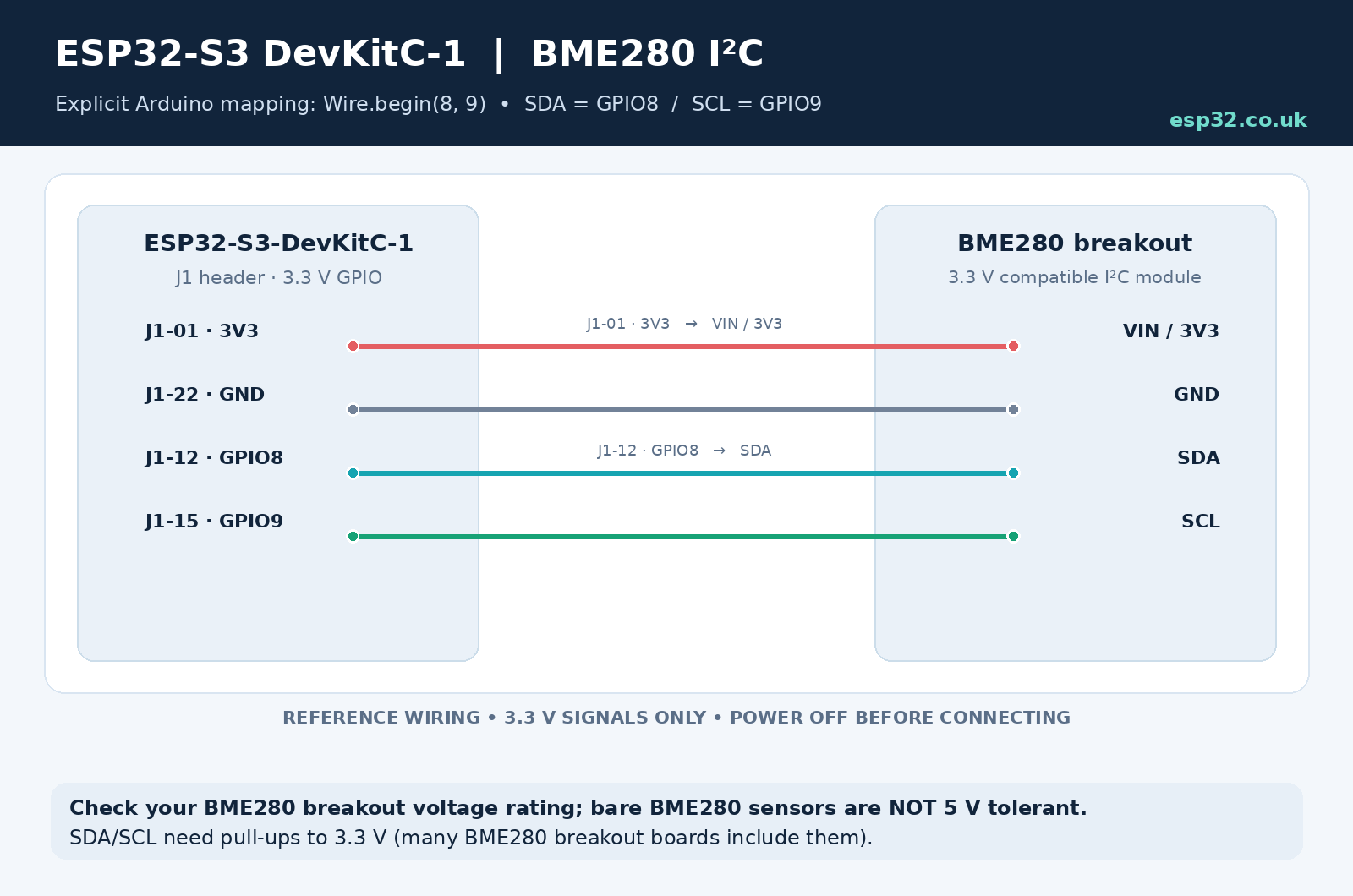
The ESP32-S3 does not force you to use one fixed pair of pins for I²C.
The GPIO matrix lets you route SDA and SCL to many GPIOs.
For the DevKitC-1, a clean default is:
| Function | GPIO |
|---|---|
| SDA | GPIO8 |
| SCL | GPIO9 |
These pins avoid boot, USB, UART and flash/PSRAM complications.
Arduino example:
#include <Wire.h>

void setup() {
  Wire.begin(8, 9);   // SDA, SCL
}

void loop() {
}
That gives you a predictable I²C connection for devices such as a BME280, OLED display, RTC, INA219 or other sensor.
You can choose other GPIOs if GPIO8/9 are already needed elsewhere.
SPI Pins
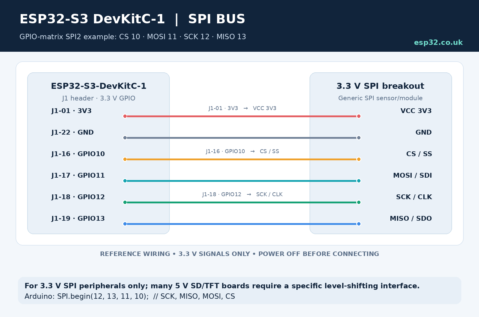
SPI is another area where the S3’s GPIO matrix provides a lot of freedom.
A particularly sensible general-purpose SPI2 mapping on the DevKitC-1 is:
| SPI signal | GPIO |
|---|---|
| CS | GPIO10 |
| MOSI | GPIO11 |
| SCK | GPIO12 |
| MISO | GPIO13 |
This group is much better as a general recommendation than GPIO35–38 because it works across the common DevKitC-1 memory variants.
It is suitable for:
- TFT displays
- SD card modules
- Ethernet controllers
- ADC/DAC chips
- RF modules
- SPI sensors
Additional control signals such as display DC, RESET and backlight can then use GPIO14–16 or another free GPIO.
For example:
| Display function | GPIO |
|---|---|
| CS | GPIO10 |
| MOSI | GPIO11 |
| SCK | GPIO12 |
| MISO | GPIO13 |
| DC | GPIO14 |
| RESET | GPIO15 |
| Backlight | GPIO16 |
Because the signals can be routed through the GPIO matrix, these aren’t mandatory pins—they are simply a very convenient layout.
For Arduino-ESP32, configure this SPI mapping explicitly rather than relying on a board package’s default SPI pins. Use SPI.begin(12, 13, 11, 10) for SCK, MISO, MOSI and CS respectively, then set GPIO10 as an output and keep it HIGH when the peripheral is deselected.
UART and Serial Pins
The ESP32-S3 has multiple UART controllers, and their signals can also be remapped.
On the DevKitC-1, UART0 is used for the normal serial console:
- GPIO43 → UART0 TX
- GPIO44 → UART0 RX
For that reason, I recommend leaving GPIO43 and GPIO44 alone unless you deliberately want to repurpose the console.
For a second serial peripheral, GPIO17 and GPIO18 form a very convenient pair:
| Function | GPIO |
|---|---|
| UART1 TX | GPIO17 |
| UART1 RX | GPIO18 |
This is useful for:
- GPS modules
- RS-485 transceivers
- energy meters
- other microcontrollers
- serial displays
- GSM/LTE modules
Arduino example:
HardwareSerial DeviceSerial(1);

void setup() {
  DeviceSerial.begin(9600, SERIAL_8N1, 18, 17);
}
Remember that Arduino’s begin() arguments are RX first, then TX.
PWM Pins
The ESP32-S3 LED PWM controller can be routed through the GPIO matrix, so most ordinary output-capable GPIOs can be used for PWM.
For LEDs, fan control, dimming and similar applications, pick from the normal safe GPIO pool rather than wasting a special-function pin.
Good examples include:
GPIO4, GPIO5, GPIO6, GPIO7, GPIO14, GPIO15, GPIO16, GPIO17, GPIO18, GPIO21 or GPIO47
For motors, relays and other inductive loads, the GPIO should drive a proper transistor, MOSFET or driver circuit rather than powering the load directly.
Practical ESP32-S3-DevKitC-1 Pin Recipes
Wi-Fi sensor with I²C and a relay
A simple arrangement that leaves all problematic pins alone:
| Function | Recommended GPIO | Notes |
|---|---|---|
| I²C SDA | GPIO8 | Sensors / OLED |
| I²C SCL | GPIO9 | Sensors / OLED |
| Relay | GPIO21 | Simple digital output |
| Button / reed switch | GPIO4 | Digital input |
| Analog sensor | GPIO1 or GPIO2 | ADC1 |
This leaves native USB, UART0, strapping pins and flash/PSRAM-related pins untouched.
SPI TFT display
A convenient mapping is:
| Function | GPIO |
|---|---|
| CS | GPIO10 |
| MOSI | GPIO11 |
| SCK | GPIO12 |
| MISO | GPIO13 |
| DC | GPIO14 |
| RESET | GPIO15 |
| Backlight | GPIO16 |
That gives you a neat sequential group on the J1 side of the board.
Native USB device with button and status indication
| Function | GPIO |
|---|---|
| USB D- | GPIO19 |
| USB D+ | GPIO20 |
| User button | GPIO4 |
| Extra status LED | GPIO5 |
For the onboard RGB LED, check your board revision first:
- original DevKitC-1 → GPIO48
- DevKitC-1 v1.1 → GPIO38
UART device plus I²C sensors
| Function | GPIO |
|---|---|
| UART RX | GPIO18 |
| UART TX | GPIO17 |
| I²C SDA | GPIO8 |
| I²C SCL | GPIO9 |
| Digital output | GPIO21 |
This combination keeps UART0 free for debugging and programming.
Pins I Would Avoid First
When starting a new DevKitC-1 project, I would not choose these pins unless there is a specific reason.
GPIO0, GPIO3, GPIO45 and GPIO46
Strapping pins. They can work after startup, but external circuitry can interfere with boot.
GPIO19 and GPIO20
Keep free when using native USB.
GPIO35, GPIO36 and GPIO37
Availability depends on the module’s flash/PSRAM configuration.
Don’t design around them unless you have checked the exact module fitted to your board.
GPIO38 and GPIO48
One is connected to the RGB LED depending on the DevKitC-1 revision.
GPIO43 and GPIO44
UART0 console and USB-to-UART interface.
GPIO39–42
Fine as GPIO when you’re not using traditional external JTAG, but I would use the completely free pins first.
ESP32-S3-DevKitC-1 Rules of Thumb
The ESP32-S3-DevKitC-1 is an extremely flexible development board once you separate the genuinely free GPIOs from pins that have additional jobs.
The practical rules are simple:
- Start with GPIO1, 2, 4–18, 21 and 47 for ordinary I/O
- Avoid GPIO0, 3, 45 and 46 for normal peripherals
- Reserve GPIO19 and 20 when using native USB
- Don’t assume GPIO35–37 are available without checking your exact module
- Check whether your RGB LED is on GPIO38 or GPIO48
- Keep GPIO43/44 free if you want the normal UART console
- Prefer ADC1 on GPIO1–10 for Wi-Fi projects
- GPIO8/9 make a convenient I²C pair
- GPIO10–13 make a convenient SPI bus
- GPIO17/18 make a convenient additional UART
Follow those rules and the ESP32-S3-DevKitC-1 becomes a very predictable platform for Wi-Fi sensors, Home Assistant nodes, relays, displays, native USB devices and general ESP32-S3 development.
The important thing isn’t memorising every alternate peripheral function printed on a pinout diagram. It is knowing which GPIOs have hidden responsibilities and choosing the uncomplicated pins first.