(LCD, encoder, RGB LED, audio, IR, “safe” pins)
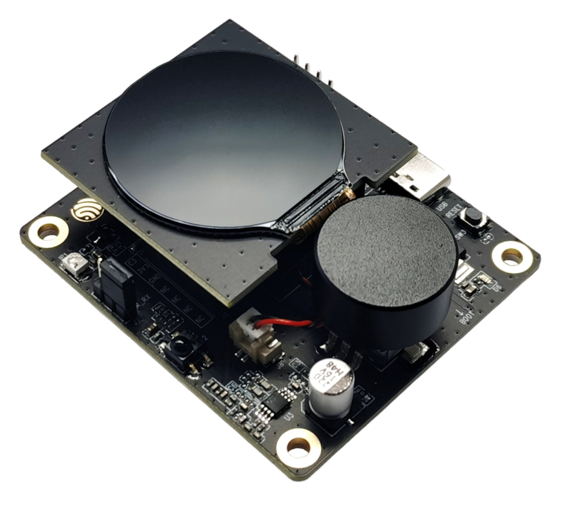
The ESP32-C3-LCDkit is a small all-in-one dev board with:
- ESP32-C3-MINI-1 module (4 MB flash, Wi-Fi + BLE)
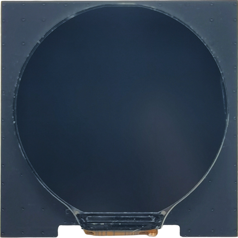
- 1.28″ 240×240 SPI LCD subboard (GC9A01 driver)
- Rotary encoder + push button
- RGB LED (WS2812)
- Speaker + audio amp
- IR transmitter + IR receiver
- USB-C for power + flashing
It’s perfect for small GUI gadgets, knobs, thermostats, timers – but many GPIOs are already “spoken for” by the LCD and other peripherals. This guide explains which pins do what, and how to safely add your own sensors or buttons.
1. High-level architecture
The kit has two boards:
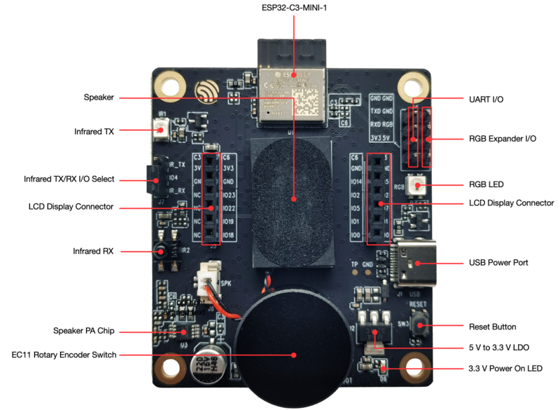
- Mainboard (ESP32-C3-LCDkit_MB)
- ESP32-C3-MINI-1 module
- Rotary encoder (A/B + switch)
- Speaker + PA
- IR TX / IR RX with jumper selector
- RGB LED
- USB-C, LDO, power LEDs
- LCD connector & “UART/RGB expander” header
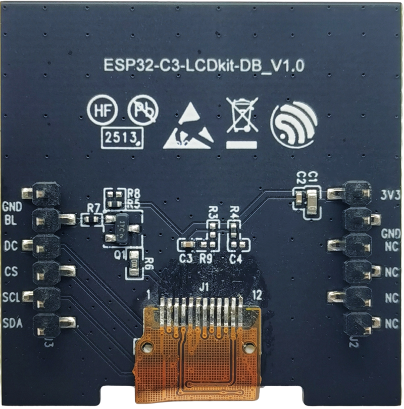
- LCD subboard (ESP32-C3-LCDkit_DB)
- 1.28″ SPI TFT 240×240 (GC9A01)
- Breakout for LCD pins: SDA, SCL, CS, DC, BL, GND, 3V3 etc.
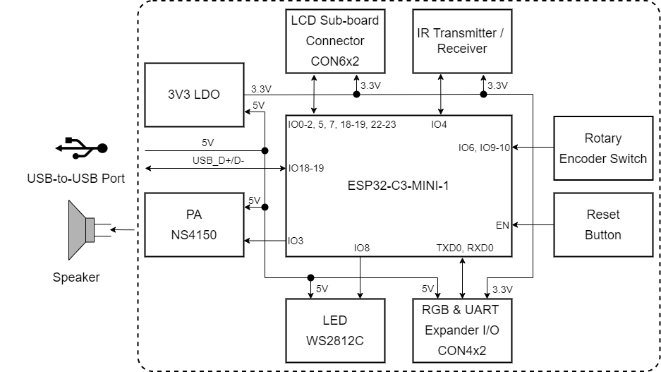
2. ESP32-C3 GPIO allocation on this kit
From Espressif’s GPIO allocation table:
| ESP32-C3 GPIO | Board function |
|---|---|
| IO0 | LCD_SDA (data line) |
| IO1 | LCD_SCL (clock) |
| IO2 | LCD_D/C |
| IO3 | AUDIO_PA (amp enable / control) |
| IO4 | IR_RX / IR_TX (via jumper) |
| IO5 | LCD_BL_CTRL (backlight) |
| IO6 | ENCODER_A (one phase) |
| IO7 | LCD_CS (chip select) |
| IO8 | RGB_LED (WS2812) |
| IO9 | ENCODER_SW (encoder push button) |
| IO10 | ENCODER_A (other phase – effectively ENCODER_B) |
| IO18 | USB_DN (native USB) |
| IO19 | USB_DP (native USB) |
| RXD0/TXD0 | Reserved (USB-serial) |
ADC-capable pins GPIO0–4 are therefore already wired to LCD / audio / IR. You can still use them (for example, read an ADC and drive the LCD from the same pin set), but you’re sharing those pins with the built-in features.
3. Power & USB
- USB-C port supplies 5 V to the board, then a 5V→3.3V LDO powers the ESP32-C3 and peripherals.
- A 3.3 V power LED shows when the board is on.
- USB-C is used both for power and flashing/debug via the on-board USB interface (native USB + USB-serial).
Recommended: use a 5V / 2A USB supply, as the LCD, speaker and Wi-Fi can draw noticeable current.
4. LCD connections (SPI)
The LCD subboard is a SPI display (GC9A01). On the mainboard, the LCD pins are wired:
- LCD_SDA → GPIO0 (MOSI)
- LCD_SCL → GPIO1 (SCLK)
- LCD_D/C → GPIO2 (data/command)
- LCD_CS → GPIO7 (chip select)
- LCD_BL_CTRL → GPIO5 (backlight PWM/on-off)
- 3V3 / GND power from mainboard
So your main SPI LCD bus is:
| Signal | GPIO |
|---|---|
| MOSI | 0 |
| SCLK | 1 |
| CS | 7 |
| D/C | 2 |
The official ESP-IDF example for this kit already has these pins configured for the GC9A01 driver.
5. Rotary encoder & button
The board includes an EC11 rotary encoder with push button. Wiring:
- ENCODER_A → GPIO6
- ENCODER_B → GPIO10 (listed as ENCODER_A in the table but used as the other phase)
- ENCODER_SW → GPIO9 (push button to ground, with pull-up)
So in code you typically:
- Attach interrupts to GPIO6 and GPIO10 to track rotation.
- Read GPIO9 as a digital input with internal pull-up to detect button press.
Example (Arduino-style pseudo):
const int ENC_A = 6;
const int ENC_B = 10;
const int ENC_SW = 9;

volatile int encoderPos = 0;

void IRAM_ATTR handleEnc() {
  int a = digitalRead(ENC_A);
  int b = digitalRead(ENC_B);
  if (a == b) encoderPos++;
  else        encoderPos--;
}

void setup() {
  pinMode(ENC_A, INPUT_PULLUP);
  pinMode(ENC_B, INPUT_PULLUP);
  pinMode(ENC_SW, INPUT_PULLUP);

  attachInterrupt(digitalPinToInterrupt(ENC_A), handleEnc, CHANGE);
  attachInterrupt(digitalPinToInterrupt(ENC_B), handleEnc, CHANGE);
}
(This board is mainly targeted at ESP-IDF, but the logic is the same.)
6. RGB status LED (GPIO8)
There’s a WS2812B RGB LED wired to GPIO8:
- Powered from 3.3 V.
- Single-wire data input on GPIO8.
You control it with NeoPixel / WS2812 style libraries (Adafruit_NeoPixel, RMT-based driver in ESP-IDF, etc.).
Minimal ESP-IDF style idea:
- Configure RMT channel on GPIO8.
- Use the “Rainbow / RGB LED” example from the
esp32_c3_lcdkitcomponent.
7. Audio output (GPIO3)
The board has a speaker + PA (NS4150). The PA is driven from GPIO3 (AUDIO_PA).
- In ESP-IDF examples, the I²S / DAC output is routed through this path.
- You can toggle GPIO3 to mute/unmute, or feed a PWM / DAC waveform depending on the example.
This is amazing for making sound effects, alarms, “clicks” in your GUI.
8. Infrared TX / RX (GPIO4)
The kit has both IR transmitter and IR receiver on GPIO4, selected by a jumper:
- A small header labeled something like IR_TX / IR_RX select
- You place the jumper to choose TX or RX using the same GPIO.
In code you typically use:
- RMT TX for sending IR remote codes.
- RMT RX for decoding incoming IR signals.
Espressif’s docs include separate schematics and part numbers for the IR LED and receiver.
9. USB & serial
There are two USB-related parts:
- Native USB (IO18 / IO19 as USB_DN / USB_DP)
- Used by the Type-C port for direct USB device functionality (CDC, HID, etc.).
- UART0 (TXD0, RXD0)
- Connected internally to the USB interface for flashing and Serial Monitor.
- Marked as “reserved” in the GPIO allocation table – not for general use.
From the user perspective you just:
Serial.begin(115200);
or in ESP-IDF use idf.py monitor, and the board just shows logs via USB-C.
10. “Safe pins” for expansion
Because this board is tightly integrated, there aren’t spare header rows like DevKitC. But you do get an “UART & RGB expander I/O” header on the side:
This header breaks out:
- Power pins (3V3, GND)
- UART (TXD0 / RXD0)
- RGB data (GPIO8)
So for adding things like:
- An external WS2812 LED strip (chained from the onboard RGB LED)
- A UART peripheral (e.g. external MCU, RS-485 adapter)
…you plug into this header.
What about extra GPIOs?
Most GPIOs are already dedicated:
- 0,1,2,5,7 → LCD
- 3 → audio
- 4 → IR
- 6,10,9 → encoder
- 8 → RGB
- 18,19 → USB
If you really need another GPIO:
- You can share existing lines (e.g. use LCD_CS as a chip-select for another SPI device on the same bus),
- Or tap the module pads / test pads (advanced, soldering-iron territory).
This is why the LCDkit is best treated as an application-specific board (GUI + encoder + audio + IR), not a general “many spare GPIO” board.
11. Typical project wiring patterns
Given the tight GPIO allocation, “wiring patterns” are mostly internal, but here’s how you logically think about it:
11.1 Simple GUI knob (no extra hardware)
- Use the official ESP-IDF example for ESP32-C3-LCDkit.
- Keep all pins as-is (LCD, encoder, RGB, speaker, IR).
- Customize only graphics + logic in code.
11.2 Add an external WS2812 strip
- Chain extra LEDs to GPIO8 through the expander header.
- Power strip from 3V3 (small number of LEDs) or separate 5V supply (with common GND).
- Keep the LED count small (this is a demo board, not a giant LED driver).
11.3 Add a simple UART sensor
- Use TXD0 / RXD0 on expander header only when you don’t need USB serial at the same time, or bit-bang another UART over existing GPIOs (e.g. share LCD_SDA/SCL when LCD idle).
- In practice, for beginners: stick to USB serial and avoid external UART on this board.
12. Summary
The ESP32-C3-LCDkit is:
- A GUI knob dev board, not a generic GPIO breakout.
- LCD, encoder, RGB LED, audio and IR consume almost every GPIO.
- The main “user-tunable” things are how you use:
- The rotary encoder + button (GPIO6/10/9)
- The RGB LED (GPIO8)
- The speaker (GPIO3)
- The LCD SPI bus (GPIO0/1/2/5/7)