(Safe pins, ADC, I²C, SPI, UART, LED)
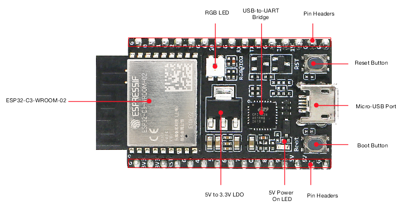
The ESP32-C3-DevKitC-02 is Espressif’s small RISC-V dev board based on the ESP32-C3-WROOM-02 module (4 MB flash, Wi-Fi + BLE). Almost all useful GPIOs are broken out on the two headers J1 and J3.
This guide focuses on which pins you can safely use, and how to wire ADC, I²C, SPI, UART and the onboard RGB LED.
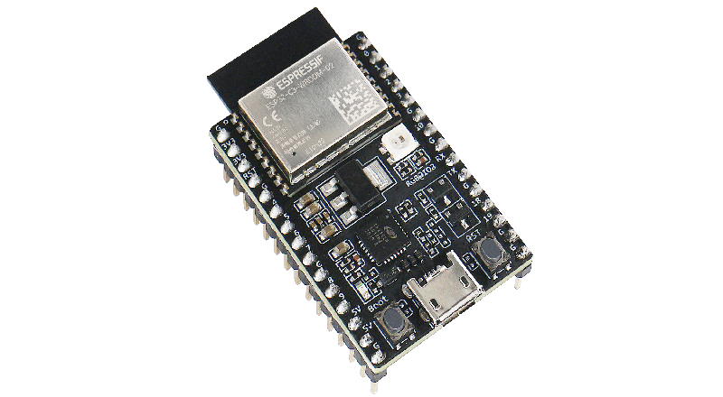
1. Board overview
Key features (DevKitC-02):
- MCU: ESP32-C3 (32-bit single-core RISC-V @ up to 160 MHz)
- Wireless: 2.4 GHz Wi-Fi (b/g/n) + BLE 5
- Flash: 4 MB (SPI)
- Power:
- via Micro-USB
- or 5 V pin
- or 3V3 pin
- Onboard USB-to-UART bridge (CP2102/CH340-type, depends on revision)
- BOOT button (GPIO9) + RESET button (EN/CHIP_PU)
- Onboard RGB LED on GPIO8
⚠️ All I/O is 3.3 V only. Pins are not 5 V tolerant – only the 5 V pin is meant to see 5 V (goes to the regulator).
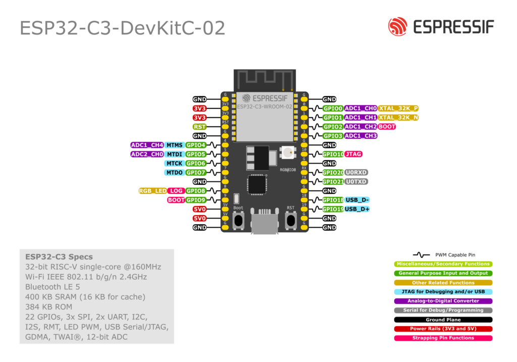
2. Pinout summary (J1 / J3 headers)
Left header (J1)
From bottom (USB side) to top (module side):
| J1 Pin | Name | Description / Functions (main ones) |
|---|---|---|
| 1 | GND | Ground |
| 2 | 3V3 | 3.3 V output (from on-board LDO) |
| 3 | 3V3 | 3.3 V output (same rail) |
| 4 | RST | EN / CHIP_PU – reset input (active HIGH enable) |
| 5 | GND | Ground |
| 6 | GPIO4 | ADC1_CH4, FSPIHD, MTMS – good GPIO/ADC |
| 7 | GPIO5 | ADC2_CH0, FSPIWP, MTDI – GPIO/ADC2 (Wi-Fi caveat) |
| 8 | GPIO6 | FSPICLK, MTCK – good GPIO/SPI SCLK |
| 9 | GPIO7 | FSPID, MTDO – good GPIO/SPI MOSI/CS |
| 10 | GND | Ground |
| 11 | GPIO8 | Onboard RGB LED data, also strapping pin |
| 12 | GPIO9 | BOOT button, strapping pin |
| 13 | 5V | 5 V from USB (or input if powering externally) |
| 14 | 5V | Same 5 V rail |
| 15 | GND | Ground |
Right header (J3)
From bottom (USB side) to top:
| J3 Pin | Name | Description / Functions (main ones) |
|---|---|---|
| 1 | GND | Ground |
| 2 | GPIO0 | ADC1_CH0, XTAL_32K_P – GPIO/ADC, also RTC 32 kHz |
| 3 | GPIO1 | ADC1_CH1, XTAL_32K_N – GPIO/ADC, also RTC 32 kHz |
| 4 | GPIO2 | ADC1_CH2, FSPIQ – GPIO/ADC, strapping |
| 5 | GPIO3 | ADC1_CH3 – GPIO/ADC |
| 6 | GND | Ground |
| 7 | GPIO10 | FSPICS0 – good GPIO / SPI CS |
| 8 | GND | Ground |
3. Safe GPIOs (quick reference)
Safest general-purpose digital pins (no special boot quirks, broken out, not tied to buttons/LED):
GPIO0, GPIO1, GPIO3, GPIO4, GPIO6, GPIO7, GPIO10
They are perfect for: buttons, relays, MOSFET gates, SPI/I²C/UART signals, etc.
Pins that are usable but need care
- GPIO2, GPIO8, GPIO9 – strapping pins
- Their level at reset controls boot configuration.
- On this board:
- GPIO8 also drives the onboard RGB LED.
- GPIO9 is wired to the BOOT button (pulled up, button to GND).
- You can use them after boot, but avoid:
- heavy loads
- large capacitors
- strong external pull-downs that might hold the pin low during reset.
- GPIO5 (ADC2_CH0) – the only ADC2 pin.
- ADC2 is shared with Wi-Fi; reading it while Wi-Fi is active can fail.
- Best used for slow sensors or when Wi-Fi traffic is light.
Pins you should not use
- RST / EN (CHIP_PU) – reset only, don’t use as a GPIO.
- 5V / 3V3 / GND – power pins only.
- Internal flash pins (GPIO12–17) and USB D± pins (18,19) are not broken out on this dev board.
4. ADC pins (analog inputs)
ESP32-C3 integrates two 12-bit SAR ADCs with 6 total channels:
- ADC1 (recommended):
- GPIO0, GPIO1, GPIO2, GPIO3, GPIO4
- ADC2:
- GPIO5
Tips:
- Use GPIO0–4 wherever possible, especially in Wi-Fi projects.
- ADC is 12-bit (0–4095). Max voltage depends on attenuation (up to ~2.5 V at 11 dB).
- Add a small capacitor (e.g. 100 nF) from the ADC pin to GND for more stable readings.
Example – read a potentiometer on GPIO3 (ADC1_CH3):
const int ADC_PIN = 3; // GPIO3

void setup() {
  Serial.begin(115200);
  analogReadResolution(12);       // 0–4095
}

void loop() {
  int raw = analogRead(ADC_PIN);
  float volts = raw * 3.3 / 4095.0;  // approx, depends on attenuation
  Serial.printf("ADC raw=%d  V=%.2f\n", raw, volts);
  delay(500);
}
5. Onboard RGB LED (GPIO8)
The DevKitC-02 includes a single addressable RGB LED (WS2812-style) on GPIO8.
- Powered from 3.3 V.
- Use a NeoPixel / FastLED library and set data pin = 8.
- Remember: GPIO8 is also a strapping pin, but the onboard circuitry is designed not to break boot.
Example – blink the onboard LED (as plain digital, not RGB):
Some Arduino cores let you treat it as a normal output:
const int LED_PIN = 8;

void setup() {
  pinMode(LED_PIN, OUTPUT);
}

void loop() {
  digitalWrite(LED_PIN, HIGH);
  delay(500);
  digitalWrite(LED_PIN, LOW);
  delay(500);
}
For full RGB control, use Adafruit_NeoPixel or FastLED with 1 pixel on pin 8.
6. I²C pins (SDA / SCL)
The ESP32-C3’s I²C peripheral is fully remappable using the GPIO matrix – you can use almost any free GPIO.
On this board, a safe and convenient I²C pair is:
- SDA = GPIO4 (J1-6)
- SCL = GPIO5 or GPIO6 (J1-7 or J1-8)
Avoid using GPIO9 as SCL (strapping + BOOT button) unless you really know what you’re doing.
Example Arduino I²C setup:
#include <Wire.h>

#define SDA_PIN 4
#define SCL_PIN 6

void setup() {
  Wire.begin(SDA_PIN, SCL_PIN);
  Serial.begin(115200);
  Serial.println("I2C started on GPIO4 (SDA) / GPIO6 (SCL)");
}
7. SPI pins
ESP32-C3 has one general-purpose SPI controller (SPI2) in addition to the flash SPI. Pins can be remapped, but the FSPI-labelled pins are convenient defaults.
Recommended SPI mapping on DevKitC-02:
- SCLK = GPIO6 (J1-8)
- MOSI = GPIO7 (J1-9)
- MISO = GPIO4 (J1-6)
- CS = GPIO10 (J3-7)
This keeps all SPI signals on the left/right mid-section and avoids strapping pins.
8. UART (serial) pins
- The main USB-serial connection uses the ESP32-C3’s UART0 internally (TX/RX pins aren’t broken out – they go straight to the USB-UART bridge).
- For an extra UART (e.g.
Serial1in Arduino) you can map TX/RX to any free GPIO.
Typical mapping for a second UART:
- TX = GPIO7
- RX = GPIO6
9. Deep-sleep & wake-up notes
- Any GPIO can generate interrupts while the chip is running.
- For deep-sleep, ESP32-C3 uses specific RTC-capable pins (several of GPIO0–5 can be used depending on mode). Details are in the ESP32-C3 datasheet, but a practical rule:
- GPIO0–5 are the best candidates for wake-up sources.
10. “Cheat sheet” – what to use for what
- Digital outputs / inputs (safe):
- GPIO0, 1, 3, 4, 6, 7, 10
- ADC inputs:
- Best: GPIO0–4
- Extra (Wi-Fi-sensitive): GPIO5 (ADC2)
- Onboard LED:
- GPIO8 (WS2812 RGB)
- I²C (suggested):
- SDA: GPIO4
- SCL: GPIO6 (or 5)
- SPI (suggested):
- SCLK: GPIO6, MOSI: GPIO7, MISO: GPIO4, CS: GPIO10
- Boot-sensitive (be gentle):
- GPIO2, GPIO8, GPIO9