(Safe pins, ADC, I²C, SPI, UART, RGB LED)
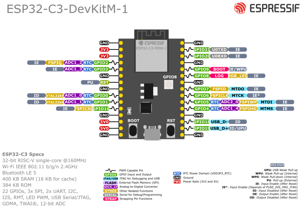
The ESP32-C3-DevKitM-1 is Espressif’s tiny RISC-V dev board based on the ESP32-C3-MINI-1 / MINI-1U module – a very compact Wi-Fi + BLE module with 4 MB flash.
It’s designed to plug into a breadboard and expose almost all ESP32-C3 GPIOs on two 15-pin headers (J1 and J3). This guide focuses on which pins are safe to use, and how to wire ADC, I²C, SPI, UART and the onboard RGB LED.
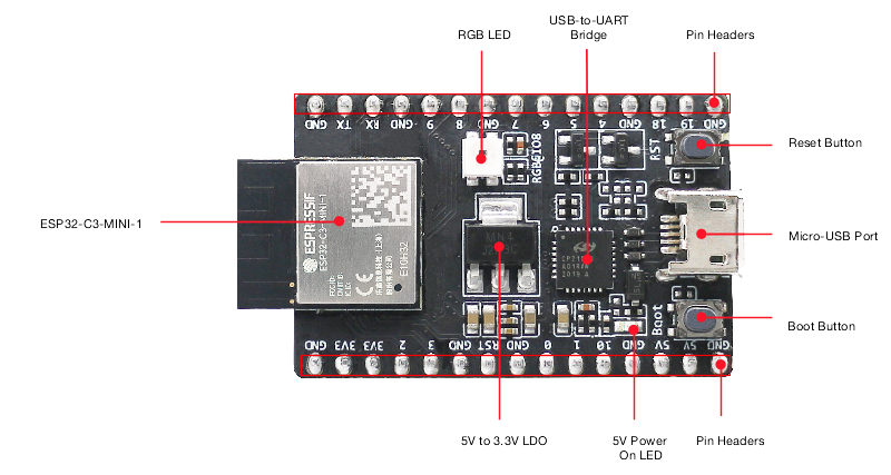
1. Board overview
Key specs:
- MCU: ESP32-C3 (single-core 32-bit RISC-V up to 160 MHz)
- Wireless: 2.4 GHz Wi-Fi (802.11 b/g/n) + BLE 5 (LE)
- Flash: 4 MB SPI flash
- Power:
- Micro-USB (default)
- or 5V pin
- or 3V3 pin
- USB-to-UART bridge (for flashing + Serial Monitor)
- BOOT button (enter download mode)
- RST button (reset / EN)
- Onboard RGB LED controlled via a single GPIO (WS2812-style)
All GPIOs are 3.3 V only (not 5 V tolerant).
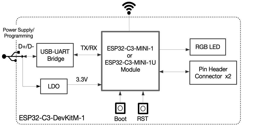
2. Power & control pins
From Espressif’s hardware reference:
- 5V – USB 5 V rail; can be used as input if powering from an external 5 V source.
- 3V3 – regulated 3.3 V from onboard LDO (or input if you supply your own 3.3 V).
- GND – ground.
- RST / EN / CHIP_PU – active-high enable; pulling LOW resets/powers down the chip.
- BOOT – used together with reset to enter UART download mode.
You normally do not use RST or BOOT as GPIOs.
3. Pin headers J1 & J3
Espressif breaks out most GPIOs on J1 (left) and J3 (right). The exact order is given in the user guide tables.
High-level view (logical, not physical order):
- GPIO0–GPIO10 – ADC-capable, general I/O.
- GPIO18, 19 – USB D- / D+ (native USB) – not broken out on this board.
- GPIO20, 21 – I/O + UART signals depending on config; at least one is usually used for the RGB LED on DevKitM-1 boards.
The ESP32-C3-MINI-1 module itself exposes 22 pads, but DevKitM-1 uses a subset to keep the board compact.
4. Safe GPIOs for general use
From the Espressif pin tables and module docs:
The following pins are good, boring choices for digital input/output, PWM, etc.:
- GPIO0 – ADC1_CH0, also XTAL_32K_P (RTC), safe as GPIO/ADC.
- GPIO1 – ADC1_CH1, XTAL_32K_N (RTC).
- GPIO3 – ADC1_CH3, general purpose.
- GPIO4 – ADC1_CH4, FSPIHD (can be used as GPIO when not re-routed).
- GPIO6 – FSPICLK, but available as GPIO on DevKitM-1.
- GPIO7 – FSPID, also good GPIO.
- GPIO10 – FSPICS0, good as chip-select or general output.
These are the primary “safe” pool to start from.
Pins that need extra care
- GPIO2 – ADC1_CH2 and strapping pin; level at reset selects boot mode.
- GPIO8 & GPIO9 – also strapping pins (boot configuration).
- GPIO5 – ADC2_CH0; ADC2 is shared with Wi-Fi, so reads can fail when Wi-Fi is active.
You can use these after boot, but:
- Avoid strong pull-downs, big capacitors or heavy loads that could force them low at reset.
- Expect ADC reads on GPIO5 to be less reliable under heavy Wi-Fi usage.
5. Boot / strapping pins
On ESP32-C3, the main strapping pins are:
- GPIO2 – controls boot mode configuration.
- GPIO8 – influences download-boot settings and logging.
- GPIO9 – BOOT button is tied here; pulled up, button shorts to GND.
At reset, the ROM samples these pins to decide whether to:
- Boot from flash (normal)
- Enter serial download mode
- Output boot messages, etc.
Rule of thumb:
For beginners, keep GPIO2, GPIO8, GPIO9 for internal use (BOOT button, LED) and don’t wire external circuitry that might drag them low at reset.
6. ADC pins
ESP32-C3 has ADC1 (5 channels) and ADC2 (1 channel):
- ADC1: GPIO0, GPIO1, GPIO2, GPIO3, GPIO4
- ADC2: GPIO5
Best practice:
- Prefer GPIO0–4 for analog sensors (thermistor, LDR, potentiometer, etc.).
- Use GPIO5 (ADC2) only if you understand the Wi-Fi conflict (reads can fail if Wi-Fi is busy).
Resolution is up to 12 bits (0–4095); usable voltage depends on attenuation (typically up to ~2.4–3.0 V). Keep inputs ≤ 3.3 V or use a resistor divider.
7. Onboard RGB LED
DevKitM-1 has a WS2812-style RGB LED on the board, marked “RGB”. It’s driven from a single GPIO (commonly GPIO8 or GPIO2 depending on revision/schematic).
- It’s powered from 3.3 V.
- To control colours you use a library like Adafruit_NeoPixel or FastLED.
Example (assuming LED on GPIO8):
#include <Adafruit_NeoPixel.h>

#define LED_PIN 8
#define LED_COUNT 1

Adafruit_NeoPixel rgb(LED_COUNT, LED_PIN, NEO_GRB + NEO_KHZ800);

void setup() {
  rgb.begin();
  rgb.show(); // turn off
}

void loop() {
  rgb.setPixelColor(0, rgb.Color(255, 0, 0)); // red
  rgb.show();
  delay(500);

  rgb.setPixelColor(0, rgb.Color(0, 255, 0)); // green
  rgb.show();
  delay(500);

  rgb.setPixelColor(0, rgb.Color(0, 0, 255)); // blue
  rgb.show();
  delay(500);
}
Because this LED often shares a strapping GPIO, avoid adding extra external loads on that same pin.
8. I²C pins
The ESP32-C3 I²C peripheral is fully GPIO-matrixed, so you can choose almost any free GPIO.
Good default pairs on DevKitM-1:
- Option 1 (recommended):
- SDA = GPIO4
- SCL = GPIO6
- Option 2 (if 4/6 are busy):
- SDA = GPIO1
- SCL = GPIO3
Avoid GPIO2, 8, 9 for I²C unless you’re comfortable with strapping behaviour.
Arduino example:
#include <Wire.h>

void setup() {
  Wire.begin(4, 6);   // SDA, SCL
  Serial.begin(115200);
  Serial.println("I2C on GPIO4 (SDA), GPIO6 (SCL)");
}

void loop() {
  // read/write I2C sensors here
}
9. SPI pins
ESP32-C3’s SPI controller can route signals to most GPIOs, but the “FSPI” pins are particularly suited for high-speed SPI. On the DevKitM-1, these include:
- GPIO6 – FSPICLK (SCLK)
- GPIO7 – FSPID (MOSI)
- GPIO4 – FSPIHD (can use as MISO)
- GPIO10 – FSPICS0 (CS)
Suggested SPI mapping for user peripherals:
| Signal | GPIO |
|---|---|
| SCLK | GPIO6 |
| MOSI | GPIO7 |
| MISO | GPIO4 |
| CS | GPIO10 |
This keeps everything on the same side of the board and away from the most sensitive boot pins.
10. UART / Serial
On DevKitM-1 the main USB-to-UART bridge is pre-wired to the ESP32-C3’s UART0, so you just call Serial.begin() and it “just works”. The TX/RX pads of UART0 are not meant as general GPIO on this board.
If you need an extra UART (e.g. for GPS, RS-485):
- Map UART1 or remap UART0 to spare GPIOs such as GPIO7 (TX) and GPIO6 (RX).
- Configure in Arduino with something like:
HardwareSerial Serial1(1);

void setup() {
  Serial.begin(115200);               // USB serial
  Serial1.begin(9600, SERIAL_8N1, 6, 7); // RX=GPIO6, TX=GPIO7
}
11. “Starter” pin recipe (safe template)
For a typical Wi-Fi sensor node with I²C sensor, ADC input and RGB status LED:
| Function | GPIO | Notes |
|---|---|---|
| I²C SDA | GPIO4 | BME280 / SHT sensor etc. |
| I²C SCL | GPIO6 | |
| Analog input | GPIO1 | ADC1_CH1 |
| Extra digital out | GPIO7 | Relay/MOSFET or SPI MOSI |
| Extra digital in | GPIO3 | Button, reed switch |
| RGB LED (onboard) | GPIO8 | With NeoPixel/FastLED |
This combination:
- Avoids heavy use of strapping pins at reset.
- Keeps ADC on ADC1 (Wi-Fi-friendly).
- Leaves GPIO0, 2, 5, 9, 10 available for expansion.
12. Quick cheat sheet
- Safest general-purpose GPIOs:
- 0, 1, 3, 4, 6, 7, 10
- ADC inputs (ADC1):
- 0, 1, 2, 3, 4
- ADC2 (Wi-Fi-sensitive):
- 5
- Onboard RGB LED:
- Usually GPIO8 (check silkscreen / schematic for your revision).
- Boot-sensitive pins:
- 2, 8, 9 – don’t pull strongly low at reset.
- Nice I²C default:
- SDA 4, SCL 6
- Nice SPI default:
- SCLK 6, MOSI 7, MISO 4, CS 10
Stick to these sets and the ESP32-C3-DevKitM-1 becomes a very predictable little board for IoT sensors, Home Assistant nodes, and BLE gadgets, without “why won’t it boot?” surprises.