This example shows how to read touch coordinates from an STMPE610 resistive touch controller using I²C or SPI. The sketch detects touch events, reads X/Y/Z pressure data, and prints everything to Serial for debugging and calibration.
The STMPE610 is a very handy chip if you’re working with resistive touch screens. Instead of reading raw analog signals yourself, it handles all the touch processing and gives you clean digital data over I²C or SPI.
What this example does
This sketch continuously monitors the touch controller and:
- Detects when the screen is touched
- Reads X and Y coordinates
- Reads pressure (Z value)
- Prints everything to the Serial Monitor
- Clears the interrupt flags
It’s basically a raw touch reader, perfect for testing and calibration before building a UI.
Supported communication modes
The STMPE610 supports three communication options:
1. I²C (default in this example)
Adafruit_STMPE610 touch = Adafruit_STMPE610();
- Simplest wiring
- Uses ESP32 I²C pins
- Slightly slower than SPI
2. Hardware SPI
Adafruit_STMPE610 touch = Adafruit_STMPE610(STMPE_CS);
- Faster communication
- Uses ESP32 hardware SPI pins
3. Software SPI
Adafruit_STMPE610 touch = Adafruit_STMPE610(STMPE_CS, STMPE_SDI, STMPE_SDO, STMPE_SCK);
- Flexible pin selection
- Slower than hardware SPI
ESP32 wiring (recommended)
I²C wiring (simplest)
VCC→3.3VGND→GNDSDA→GPIO21SCL→GPIO22MODE→GND(IMPORTANT for I²C)
SPI wiring (faster)
VCC→3.3VGND→GNDMOSI→GPIO23MISO→GPIO19SCK→GPIO18CS→ any GPIO (e.g.GPIO5)MODE→3.3V(IMPORTANT for SPI)
👉 After changing MODE, you must power cycle the board.
Code walkthrough
Creating the touch object
Adafruit_STMPE610 touch = Adafruit_STMPE610();
This initializes the controller in I²C mode by default.
setup()
Serial.begin(9600);
Serial.println("Adafruit STMPE610 example");
Standard Serial output for debugging.
Initializing the controller
if (! touch.begin()) {
  Serial.println("STMPE not found!");
  while(1);
}
If the chip is not detected:
- Wrong wiring
- Wrong mode (I²C vs SPI)
- Wrong address
I²C address options
touch.begin(0x41); // default
touch.begin(0x44); // if A0 = HIGH
Most boards use 0x41.
The main loop
Detecting a touch
if (touch.touched()) {
This checks if the screen is currently being pressed.
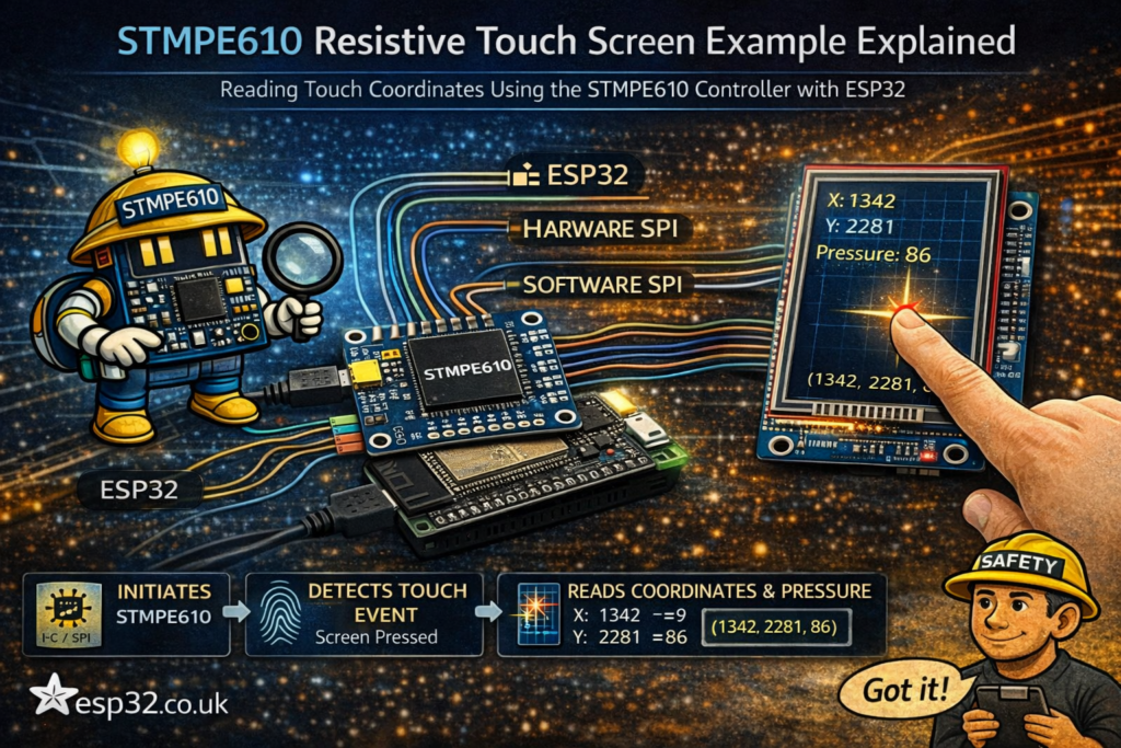
Reading touch data
touch.readData(&x, &y, &z);
This gives you:
x→ horizontal positiony→ vertical positionz→ pressure
Example output
1->(1234, 2048, 56)
Meaning:
- X = 1234
- Y = 2048
- Pressure = 56
Buffer handling
while (! touch.bufferEmpty()) {
The STMPE610 stores multiple touch samples in a buffer.
This loop:
- Reads all available samples
- Prevents data loss
- Ensures smooth tracking
Clearing interrupts
touch.writeRegister8(STMPE_INT_STA, 0xFF);
This resets interrupt flags.
Not always required, but good practice in polling setups.
Understanding the Z (pressure) value
The z value tells you how hard the screen is pressed.
Typical usage:
- Ignore very low values → noise
- Use threshold to detect valid touches
Example:
if (z > 10) {
  // valid touch
}
Important practical notes
1. Resistive touch ≠ pixel coordinates
Raw values are not screen pixels.
You must map them:
mappedX = map(x, minX, maxX, 0, screenWidth);
mappedY = map(y, minY, maxY, 0, screenHeight);
Calibration is required.
2. Orientation matters
Depending on display rotation:
- X and Y may be swapped
- Values may need inversion
3. Buffer vs single read
Using:
bufferEmpty()
is better than single reads because:
- You don’t miss fast touches
- Movement feels smoother
4. MODE pin is critical
- I²C → MODE = GND
- SPI → MODE = 3.3V
Wrong setting = no communication.
How to use this in real projects
Once this basic example works, you can:
- Build touch buttons
- Create menus or UI
- Combine with TFT display (ILI9341, ST7789, etc.)
- Use gestures (swipe, drag)
- Add touch calibration screen
Common mistakes
- Forgetting to power cycle after changing MODE
- Using wrong I²C address
- Not mapping raw coordinates
- Ignoring pressure (z) → false touches
- Not emptying buffer → laggy response
Final thoughts
The STMPE610 takes all the messy analog work of resistive touch and turns it into clean digital data. This example is simple, but it gives you everything you need to:
- Verify wiring
- Understand touch data
- Start building a UI
Once you add coordinate mapping and a display, you’re basically one step away from a full touchscreen interface.