Understanding the Adafruit_PCF8575 Button Example
Microcontrollers never seem to have enough pins. That’s where the PCF8575 comes in: a simple I²C 16-bit GPIO expander that gives you 16 extra digital pins using only 2 wires (SDA/SCL).
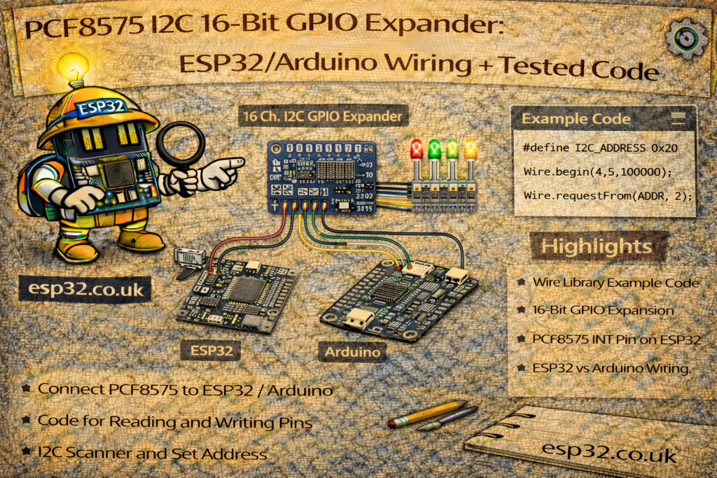
The Adafruit example you posted shows how to use a PCF8575 board as a 16-button input module, with each button wired to ground and using the chip’s internal pull-ups.
In this tutorial we’ll cover:
- What the PCF8575 does
- How to wire it to an ESP32 / Arduino
- How I/O and pull-ups work on the PCF8575
- A detailed line-by-line explanation of the example
- An extended example you can drop in your own ESP32 project
1. What is the PCF8575?
The PCF8575 is a 16-bit I/O expander:
- Communicates over I²C
- Provides 16 extra GPIO pins, labelled P0–P15 in the datasheet
- Each pin can be configured as:
- Input (with internal pull-up to VCC)
- Output (open-drain, can pull low but not drive high strongly)
Key points:
- You control all 16 bits through just SDA and SCL.
- I²C addresses are in the range 0x20–0x27, set via the A0, A1, A2 pins on the chip.
- All address pins low → 0x20 (which the example uses).
- Outputs are open-drain:
- They can pull down to GND
- “High” is actually released (the pin floats and typically relies on pull-ups)
It’s perfect for:
- Lots of buttons / switches
- Driving LEDs (with proper wiring)
- Interfacing with simple digital sensors and relays (via transistors).
2. Hardware you need
- ESP32 or Arduino (Uno, Nano, etc.)
- A PCF8575 breakout board (Adafruit or compatible)
- Up to 16 push buttons (momentary switches)
- Optional: LEDs, resistors, breadboard, jumper wires
Most PCF8575 breakout boards expose:
- VCC (often 3.3–5 V)
- GND
- SCL
- SDA
- Address pins A0, A1, A2 (sometimes as solder jumpers)
- 16 I/O pins (P0…P7 on one side, P8…P15 on the other)
3. Wiring the PCF8575 (I²C + buttons)
3.1 I²C wiring
ESP32 example:
- PCF8575
VCC→ 3.3 V (recommended to match ESP32 logic) - PCF8575
GND→ GND - PCF8575
SCL→ ESP32 SCL (e.g. GPIO 22) - PCF8575
SDA→ ESP32 SDA (e.g. GPIO 21) - PCF8575
A0,A1,A2→ GND for address0x20(same as in example)
Arduino Uno example:
- PCF8575
VCC→ 5 V (if the board supports 5 V) - PCF8575
GND→ GND - PCF8575
SCL→ A5 - PCF8575
SDA→ A4 A0–A2→ GND → address0x20
3.2 Button wiring (as in the example)
Each expander pin P0…P15 is wired like this:
- One side of button → PCF8575 pin Px
- Other side of button → GND
In software we configure each expander pin as INPUT_PULLUP, so:
- No press: internal pull-up holds the pin high → reads 1
- Button pressed: pin is connected to GND → reads 0
That’s why the example checks if (!pcf.digitalRead(p)) to detect “pressed”.
4. The Adafruit_PCF8575 example – full listing
Your example:
#include <Adafruit_PCF8575.h>

/* Example for 16 input buttons that are connected from the GPIO expander pins to ground.
 * Note the buttons must be connected with the other side of the switch to GROUND. There is
 * a built in pull-up 'resistor' on each input, but no pull-down resistor capability.
 */

Adafruit_PCF8575 pcf;

void setup() {
  Serial.begin(115200);
  while (!Serial) { delay(10); }
  Serial.println("Adafruit PCF8575 button read test");

  if (!pcf.begin(0x20, &Wire)) {
    Serial.println("Couldn't find PCF8575");
    while (1);
  }
  for (uint8_t p=0; p<16; p++) {
    pcf.pinMode(p, INPUT_PULLUP);
  }
}

void loop() {
  for (uint8_t p=0; p<16; p++) {
    if (! pcf.digitalRead(p)) {
      Serial.print("Button on GPIO #");
      Serial.print(p);
      Serial.println(" pressed!");
    }
  }
  delay(10); // a short debounce delay
}
Now let’s go through it step by step.
5. Explaining the example code
5.1 Library and object
#include <Adafruit_PCF8575.h>
...
Adafruit_PCF8575 pcf;
- Includes the Adafruit PCF8575 library.
- Creates a global
pcfobject representing one PCF8575 chip on the bus.
If you had multiple expanders with different addresses, you could create multiple objects.
5.2 setup() – Serial + I²C + PCF init
Serial.begin(115200);
while (!Serial) { delay(10); }
Serial.println("Adafruit PCF8575 button read test");
- Starts the serial monitor at 115200 baud.
while (!Serial)is a convenience for boards with native USB; on a classic ESP32 it basically just delays a bit.- Prints a startup message.
if (!pcf.begin(0x20, &Wire)) {
  Serial.println("Couldn't find PCF8575");
  while (1);
}
- pcf.begin(address, wirePort) initializes the PCF8575:
0x20is the I²C address (with A0–A2 = GND).&Wiretells it to use the default I²C bus.
- If no chip responds at that address,
begin()returnsfalse:- It prints an error and halts in
while(1).
- It prints an error and halts in
On ESP32, you should make sure you called Wire.begin(SDA, SCL) before pcf.begin if you’re using non-default pins (we’ll show that later).
for (uint8_t p=0; p<16; p++) {
  pcf.pinMode(p, INPUT_PULLUP);
}
- Loops through all 16 expander pins: 0…15.
- Sets each one to
INPUT_PULLUPon the expander, not the MCU. - The PCF8575 internally configures the line as:
- input
- with a weak pull-up to VCC
So now each pin acts like a standard INPUT_PULLUP button pin on Arduino, but over I²C.
5.3 loop() – polling the buttons
for (uint8_t p=0; p<16; p++) {
  if (! pcf.digitalRead(p)) {
    Serial.print("Button on GPIO #");
    Serial.print(p);
    Serial.println(" pressed!");
  }
}
delay(10); // a short debounce delay
- For each of the 16 pins, it calls
pcf.digitalRead(p):true/1→ pin reads HIGH (no button press)false/0→ pin reads LOW (button pressed)
- Because the pin is in INPUT_PULLUP, pressing the button connects it to GND, pulling it LOW.
That’s why the code checksif (!pcf.digitalRead(p))→ “if LOW → button pressed”. - If pressed, the code prints which “GPIO” (expander pin index) is active.
delay(10)adds a small debounce delay to avoid too many repeated messages.
This is a basic polling loop – fine for simple applications. For more advanced use, you might:
- Add software debouncing logic
- Only act when a button goes from HIGH → LOW (edge detection)
- Use the expander’s interrupt pin (if available on your breakout) to avoid constant polling.
6. ESP32-friendly version (explicit I²C pins)
Here’s a version ready to paste into an ESP32 project where you explicitly define SDA/SCL:
#include <Wire.h>
#include <Adafruit_PCF8575.h>

Adafruit_PCF8575 pcf;

// Change these if your ESP32 board uses different I2C pins
#define I2C_SDA 21
#define I2C_SCL 22

void setup() {
  Serial.begin(115200);
  delay(1000);

  Serial.println();
  Serial.println("ESP32 + PCF8575 16-button example");

  // Init I2C on ESP32
  Wire.begin(I2C_SDA, I2C_SCL);

  // PCF8575 address: 0x20 (A0=A1=A2=GND)
  if (!pcf.begin(0x20, &Wire)) {
    Serial.println("Couldn't find PCF8575 at 0x20. Check wiring and address pins!");
    while (1) {
      delay(1000);
    }
  }

  // Configure all 16 pins as inputs with pullups
  for (uint8_t p = 0; p < 16; p++) {
    pcf.pinMode(p, INPUT_PULLUP);
  }

  Serial.println("PCF8575 initialized, waiting for button presses...");
}

void loop() {
  for (uint8_t p = 0; p < 16; p++) {
    // Active-low: pressed = LOW = false
    if (!pcf.digitalRead(p)) {
      Serial.print("Button on expander GPIO #");
      Serial.print(p);
      Serial.println(" pressed!");
    }
  }

  delay(10); // basic debounce / CPU relief
}
You can also mix inputs and outputs: just call pcf.pinMode(pin, OUTPUT) for those pins and then pcf.digitalWrite(pin, LOW/HIGH).
7. Typical use cases
You can cover some scenarios in the article to make it practical:
- Lots of buttons / a keypad
- Connect 8–16 buttons to the expander instead of burning precious MCU pins.
- The example already shows a 16-button panel.
- LED matrix or indicator panel
- Use PCF8575 outputs to drive LEDs (with proper resistors, often via transistors because of open-drain outputs).
- Expanding Home Assistant / ESPHome nodes
- One ESP32 → multiple PCF8575 boards (different addresses)
- You can have 16, 32, 48… digital inputs for switches, magnetic contacts, etc.
- Industrial control panels or relay boards
- Use PCF8575 pins to control transistor/optocoupler inputs on a relay board, isolating the MCU from higher voltages.
8. Common pitfalls & tips
- Wrong address (0x20 vs others)
- Check the A0–A2 jumpers or pins.
- Use an I²C scanner sketch to see what address the board appears as.
- No pull-DOWN capability
- The expander has built-in pull-ups only.
- That’s why buttons must go to GND when pressed, and you detect LOW = pressed.
- Driving loads directly
- Remember PCF8575 outputs are open-drain.
- To drive LEDs, relays, etc., you often:
- Tie pin to LED + resistor to VCC, and use LOW to turn ON.
- Or use a transistor / MOSFET stage.
- I²C wiring length
- For long cables, use twisted pair, pull-ups of 4.7 kΩ or lower, and keep the bus relatively short.