Understanding the Adafruit ADS1X15 Example
The ADS1115 (16-bit) and ADS1015 (12-bit) are very popular external ADC chips. They talk over I²C, give you 4 analog inputs, and include a programmable gain amplifier (PGA) so you can measure both tiny and relatively high voltages very accurately.
They’re ideal when:
- The ESP32’s internal ADC noise / non-linearity annoys you
- You need more channels (4 extra inputs)
- You want stable, repeatable readings for sensors, battery monitoring, shunt resistors, etc.
In this tutorial we’ll:
- Explain what the ADS1115 / ADS1015 actually do
- Show how to wire them to an ESP32
- Explain the gain settings
- Go line-by-line through the Adafruit example you posted
- Give a cleaned-up ESP32 + ADS1115 example you can reuse in your projects
1. ADS1115 vs ADS1015 – what’s the difference?
Both chips are almost identical; the difference is resolution and speed:
- ADS1015
- 12-bit resolution
- Up to ~3300 samples per second
- ADS1115
- 16-bit resolution (much finer steps)
- Up to ~860 samples per second
Common features:
- 4 analog inputs: AIN0, AIN1, AIN2, AIN3
- Single-ended (measure each vs GND) or differential
- Programmable gain (different voltage ranges)
- I²C interface, typical default address 0x48
- Supply: ~2.0–5.5 V
For most ESP32 sensor projects, ADS1115 is the nicer choice because of the higher resolution. The Adafruit library supports both with the same API.
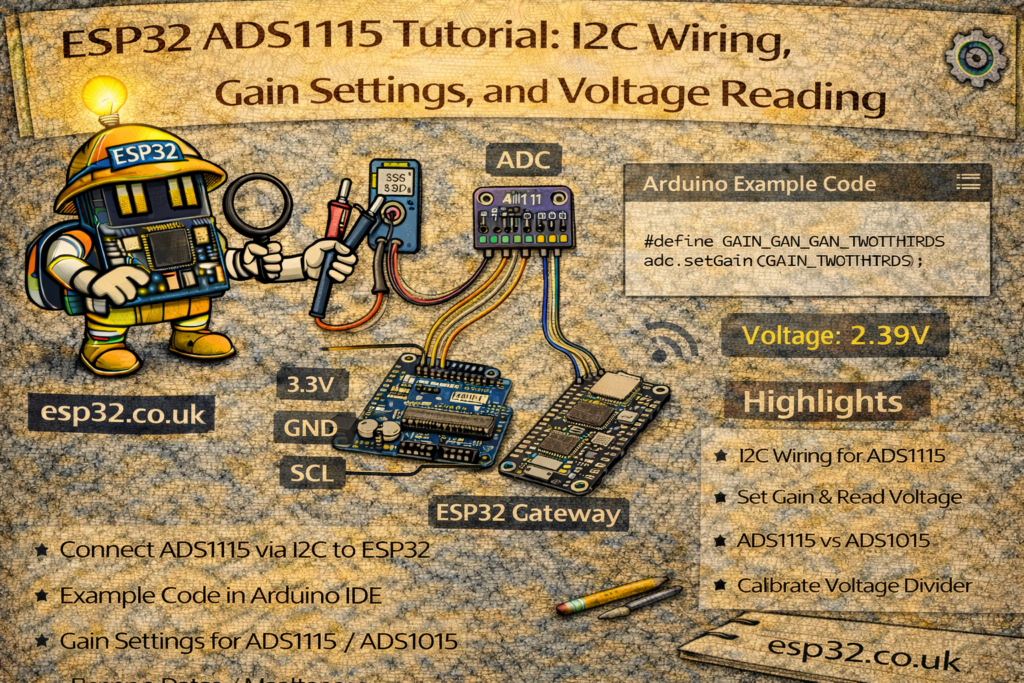
2. Hardware wiring – ADS1115 / ADS1015 to ESP32
Assume a typical breakout board (Adafruit clone style):
Power & I²C:
VDD→ 3.3 V from ESP32GND→ ESP32 GNDSCL→ ESP32 I²C SCL (e.g. GPIO 22 on many devkits)SDA→ ESP32 I²C SDA (e.g. GPIO 21 on many devkits)ADDR:- To GND → address 0x48 (default)
- To VDD → 0x49
- To SDA → 0x4A
- To SCL → 0x4B
ALERT→ optional (interrupt output for threshold/comparator mode)
Analog inputs:
AIN0–AIN3→ your sensor signals- All signals should be between GND and VDD
- For voltages above VDD, you must use a voltage divider
Example minimal test wiring:
- Potentiometer:
- One side → 3.3 V
- Other side → GND
- Wiper → AIN0
- AIN1–3 can be left unconnected for testing, or tied to GND / 3.3V via resistors.
3. Installing the Adafruit ADS1X15 library
In the Arduino IDE:
- Go to Tools → Manage Libraries…
- Search for
Adafruit ADS1X15 - Install “Adafruit ADS1X15” (by Adafruit)
Then at the top of your sketch:
#include <Wire.h>
#include <Adafruit_ADS1X15.h>
And create either:
Adafruit_ADS1015 ads;   // 12-bit
// or
Adafruit_ADS1115 ads;   // 16-bit
4. Gain settings – what do they actually do?
Inside the ADS1115/ADS1015 is a programmable gain amplifier (PGA). It selects the full-scale voltage range of the ADC:
// ads.setGain(GAIN_TWOTHIRDS);  // +/- 6.144 V
// ads.setGain(GAIN_ONE);        // +/- 4.096 V
// ads.setGain(GAIN_TWO);        // +/- 2.048 V
// ads.setGain(GAIN_FOUR);       // +/- 1.024 V
// ads.setGain(GAIN_EIGHT);      // +/- 0.512 V
// ads.setGain(GAIN_SIXTEEN);    // +/- 0.256 V
Important:
- These are input ranges of the ADC, not “allowed” input voltages.
- The real maximum you must respect is VDD + 0.3 V (and not below GND −0.3 V).
- If VDD = 3.3 V, you should never exceed ~3.6 V on any AIN pin.
So the 6.144 V range setting is still fine when powered at 3.3 V – it just assumes your input is within ±6.144 V and scales accordingly, but you must clamp it with a voltage divider if needed.
Practical choices (ESP32 @ 3.3 V):
- For sensors that output 0–3.3 V
→ useGAIN_ONE(±4.096 V), or keep the defaultGAIN_TWOTHIRDS(±6.144 V). - For small signals (0–200 mV across a shunt resistor, etc.)
→ useGAIN_SIXTEEN(±0.256 V) for maximum resolution.
If you don’t call setGain(), the Adafruit library defaults to GAIN_TWOTHIRDS.
5. The Adafruit example – explained line by line
Here’s your example:
#include <Adafruit_ADS1X15.h>

//Adafruit_ADS1115 ads;  /* Use this for the 16-bit version */
Adafruit_ADS1015 ads;     /* Use this for the 12-bit version */

void setup(void)
{
  Serial.begin(9600);
  Serial.println("Hello!");

  Serial.println("Getting single-ended readings from AIN0..3");
  Serial.println("ADC Range: +/- 6.144V (1 bit = 3mV/ADS1015, 0.1875mV/ADS1115)");

  // The ADC input range (or gain) can be changed via the following
  // functions, but be careful never to exceed VDD +0.3V max, or to
  // exceed the upper and lower limits if you adjust the input range!
  //                                                                ADS1015  ADS1115
  //                                                                -------  -------
  // ads.setGain(GAIN_TWOTHIRDS);  // 2/3x gain +/- 6.144V  1 bit = 3mV      0.1875mV (default)
  // ads.setGain(GAIN_ONE);        // 1x gain   +/- 4.096V  1 bit = 2mV      0.125mV
  // ads.setGain(GAIN_TWO);        // 2x gain   +/- 2.048V  1 bit = 1mV      0.0625mV
  // ads.setGain(GAIN_FOUR);       // 4x gain   +/- 1.024V  1 bit = 0.5mV    0.03125mV
  // ads.setGain(GAIN_EIGHT);      // 8x gain   +/- 0.512V  1 bit = 0.25mV   0.015625mV
  // ads.setGain(GAIN_SIXTEEN);    // 16x gain  +/- 0.256V  1 bit = 0.125mV  0.0078125mV

  if (!ads.begin()) {
    Serial.println("Failed to initialize ADS.");
    while (1);
  }
}

void loop(void)
{
  int16_t adc0, adc1, adc2, adc3;
  float volts0, volts1, volts2, volts3;

  adc0 = ads.readADC_SingleEnded(0);
  adc1 = ads.readADC_SingleEnded(1);
  adc2 = ads.readADC_SingleEnded(2);
  adc3 = ads.readADC_SingleEnded(3);

  volts0 = ads.computeVolts(adc0);
  volts1 = ads.computeVolts(adc1);
  volts2 = ads.computeVolts(adc2);
  volts3 = ads.computeVolts(adc3);

  Serial.println("-----------------------------------------------------------");
  Serial.print("AIN0: "); Serial.print(adc0); Serial.print("  "); Serial.print(volts0); Serial.println("V");
  Serial.print("AIN1: "); Serial.print(adc1); Serial.print("  "); Serial.print(volts1); Serial.println("V");
  Serial.print("AIN2: "); Serial.print(adc2); Serial.print("  "); Serial.print(volts2); Serial.println("V");
  Serial.print("AIN3: "); Serial.print(adc3); Serial.print("  "); Serial.print(volts3); Serial.println("V");

  delay(1000);
}
5.1 Choosing your chip
//Adafruit_ADS1115 ads;  /* Use this for the 16-bit version */
Adafruit_ADS1015 ads;     /* Use this for the 12-bit version */
- Comment out one, enable the other depending on what you soldered:
- ADS1115 → uncomment
Adafruit_ADS1115 ads; - ADS1015 → leave as is
- ADS1115 → uncomment
5.2 Setup – Serial and basic info
Serial.begin(9600);
Serial.println("Hello!");

Serial.println("Getting single-ended readings from AIN0..3");
Serial.println("ADC Range: +/- 6.144V (1 bit = 3mV/ADS1015, 0.1875mV/ADS1115)");
- Starts serial at 9600 baud, prints some status messages so you know everything is alive.
- The full-scale range shown here is the default for
GAIN_TWOTHIRDS.
5.3 Gain comments
The big comment block simply documents each gain option:
- What range you get (±X V)
- What voltage per bit you get, for:
- ADS1015 (12-bit)
- ADS1115 (16-bit)
If you uncomment one of those setGain() calls, the chip will use that new range.
5.4 Initializing the chip
if (!ads.begin()) {
  Serial.println("Failed to initialize ADS.");
  while (1);
}
ads.begin()talks to the chip over I²C (default address0x48).- If it fails, it prints an error and stops.
- If it succeeds, the ADS is ready to sample.
On ESP32, if you are using custom I²C pins, you should call Wire.begin(SDA, SCL) before ads.begin().
5.5 Reading all four channels
int16_t adc0, adc1, adc2, adc3;

adc0 = ads.readADC_SingleEnded(0);
adc1 = ads.readADC_SingleEnded(1);
adc2 = ads.readADC_SingleEnded(2);
adc3 = ads.readADC_SingleEnded(3);
- Each call:
- Configures the ADC to measure one single-ended channel
- Waits for the conversion
- Returns a signed 16-bit raw value
For single-ended measurements within range:
- Values will generally be non-negative when input ≥ 0 V
- If the input somehow goes slightly below 0 V (not recommended) you can get negative values.
5.6 Converting to volts
volts0 = ads.computeVolts(adc0);
...
computeVolts()takes:- The raw ADC value
- The current gain setting
- Knows if you’re using ADS1015 or ADS1115
And returns a floating-point voltage in volts.
No need to manually calculate scale factors; just set the correct gain and call computeVolts().
5.7 Printing the results
Serial.println("-----------------------------------------------------------");
Serial.print("AIN0: "); Serial.print(adc0); Serial.print("  "); Serial.print(volts0); Serial.println("V");
...
delay(1000);
- You get one line per channel: raw counts + volts.
delay(1000)means one reading per second.
You can change the delay to whatever you want (100 ms, 10 s, etc.).
6. ESP32-friendly ADS1115 example (ready to use)
Here’s a version specifically tuned for ESP32 + ADS1115 @ GAIN_ONE (0–4.096 V).
You can paste this directly into Arduino IDE:
#include <Wire.h>
#include <Adafruit_ADS1X15.h>

Adafruit_ADS1115 ads;  // Use ADS1115 (16-bit)

void setup() {
  Serial.begin(115200);
  delay(1000);

  Serial.println();
  Serial.println("ESP32 + ADS1115 single-ended example");

  // Use ESP32 hardware I2C pins (change to match your board)
  // Commonly: SDA = 21, SCL = 22 on classic devkits
  Wire.begin(21, 22);

  // Set gain so full-scale range is +/-4.096V (good for 0-3.3V sensors)
  ads.setGain(GAIN_ONE);

  if (!ads.begin(0x48)) {   // 0x48 is the default I2C address
    Serial.println("Failed to find ADS1115 at 0x48. Check wiring and address!");
    while (1) {
      delay(1000);
    }
  }

  Serial.println("ADS1115 initialized.");
  Serial.println("Using GAIN_ONE (+/- 4.096 V).");
}

void loop() {
  int16_t adc0 = ads.readADC_SingleEnded(0);
  int16_t adc1 = ads.readADC_SingleEnded(1);
  int16_t adc2 = ads.readADC_SingleEnded(2);
  int16_t adc3 = ads.readADC_SingleEnded(3);

  float v0 = ads.computeVolts(adc0);
  float v1 = ads.computeVolts(adc1);
  float v2 = ads.computeVolts(adc2);
  float v3 = ads.computeVolts(adc3);

  Serial.println("-------------------------------------------------");
  Serial.printf("AIN0: %6d  %.4f V\n", adc0, v0);
  Serial.printf("AIN1: %6d  %.4f V\n", adc1, v1);
  Serial.printf("AIN2: %6d  %.4f V\n", adc2, v2);
  Serial.printf("AIN3: %6d  %.4f V\n", adc3, v3);

  delay(1000);
}
You can adapt:
- The I²C pins in
Wire.begin(…) - The gain in
ads.setGain(...) - The I²C address in
ads.begin(0x48)if you changedADDR.
7. Typical use cases
A few project ideas you can mention at the end of the article:
- Battery monitor
- Voltage divider into one channel for 0–12 V or 0–24 V batteries.
- Use ADS1115 for high resolution SOC estimation.
- Current sensing via shunt resistor
- Measure the small voltage across a shunt using GAIN_SIXTEEN.
- Compute current = V / R.
- Multi-sensor node for ESP32 / Home Assistant
- Up to 4 analog sensors with good resolution and stability.
- Temperature, pressure, soil moisture, light sensors, etc.
- Precision knob or sensor reading
- Potentiometer input to ADS1115 for very fine position reading.
8. Troubleshooting checklist
If you see “Failed to initialize ADS.”:
- Check GND is common between ESP32 and ADS board
- Check VDD is actually connected (3.3 V or 5 V)
- Confirm SDA/SCL pins match your
Wire.begin(...)configuration - Confirm ADDR wiring matches the address in
ads.begin(address) - Try scanning I²C with an I²C scanner sketch to see what address the board responds to
If readings look noisy:
- Add a 100 nF capacitor from AINx to GND near the board
- Use shielded/twisted pair for long sensor wires
- Try a higher gain for small signals, or more averaging in software