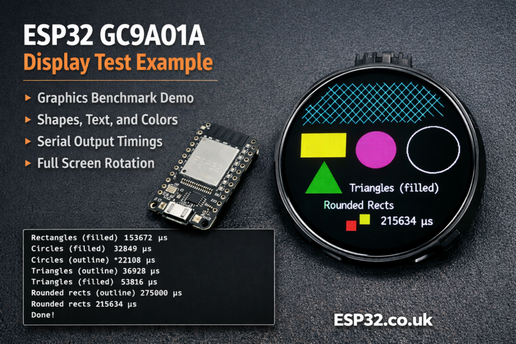
This example is the classic Adafruit graphics demo for the GC9A01A round TFT display. It initializes the display over SPI, runs several drawing benchmarks, prints the timing results to Serial, and then keeps rotating a text demo so you can confirm that your screen is wired and configured correctly.
The GC9A01A is a very common 240×240 round SPI TFT controller used in circular displays. If you have one of those popular round modules and want a quick way to test colours, text rendering, shapes, and rotation, this example is one of the best first sketches to try.
What this sketch does
This example is not meant to be a real application UI. It is mainly a display test and benchmark.
It does a few useful things:
- Initializes the GC9A01A display
- Enables the backlight if a backlight pin is defined
- Draws text in different colours and sizes
- Draws lines, rectangles, circles, triangles, and rounded rectangles
- Measures how long each graphics test takes
- Prints the timings to the Serial Monitor
- Rotates the display through all 4 orientations in the
loop()
In other words, it is a quick way to check that your display is alive, your SPI wiring works, and the library is talking properly to the panel.
Libraries used
The sketch uses three libraries:
SPI.hAdafruit_GFX.hAdafruit_GC9A01A.h
Adafruit_GFX is the general graphics library that provides text and shape drawing functions.
Adafruit_GC9A01A is the display-specific driver for the GC9A01A controller.
Install both Adafruit libraries from the Arduino Library Manager before compiling.
Typical ESP32 wiring for a GC9A01A display
The example code includes pin definitions for a Seeed XIAO RP2040 round display setup, but on an ESP32 you will usually want your own pin mapping.
A common hardware SPI wiring example for ESP32 is:
VCC→3.3VGND→GNDSCL/CLK→GPIO18SDA/MOSI→GPIO23CS→GPIO5DC→GPIO27RST→ENor a spare GPIO, depending on moduleBL→3.3Vor a spare GPIO if you want software backlight control
If you want to adapt the sketch for a typical ESP32, the pin definitions would often look like this:
#define TFT_DC 27
#define TFT_CS 5
#define TFT_BL 4
Then the display object stays the same:
Adafruit_GC9A01A tft(TFT_CS, TFT_DC);
This constructor uses hardware SPI, which is the fast and correct choice for this kind of display.
How the sketch works
Pin selection
At the top of the file, the sketch checks whether it is being compiled for a specific board:
#if defined(ARDUINO_SEEED_XIAO_RP2040)
If that board is detected, it uses the pin mapping for the Seeed round display setup.
Otherwise, it falls back to generic pin definitions:
#define TFT_DC  9
#define TFT_CS 10
That means on most ESP32 boards, you will need to edit these pins.
Display object creation
This line creates the TFT object:
Adafruit_GC9A01A tft(TFT_CS, TFT_DC);
This tells the library which chip select and data/command pins are used. The actual SPI clock and MOSI pins come from the board’s hardware SPI pins.
setup()
The setup() function does all the initialization and benchmarking.
First it opens Serial:
Serial.begin(9600);
Serial.println("GC9A01A Test!");
Then it initializes the display:
tft.begin();
If a backlight pin exists, it turns it on:
pinMode(TFT_BL, OUTPUT);
digitalWrite(TFT_BL, HIGH);
After that, the sketch runs each graphics benchmark one by one and prints the execution time in microseconds.
For example:
Serial.print(F("Screen fill              "));
Serial.println(testFillScreen());
So when you open the Serial Monitor, you will see timing values for each drawing test.
What each test function does
testFillScreen()
This fills the entire display with several colours:
- Black
- Red
- Green
- Blue
- Black again
It is a simple way to verify that the whole panel updates correctly and that the colour order is right.
testText()
This demonstrates text rendering with different:
- Colours
- Sizes
- Numeric formats
- Line spacing
It writes some sample text, including the famous Adafruit nonsense phrase:
- “Groop”
- “I implore thee…”
- and the rest of the classic demo text
This part is useful for checking font scaling and readability.
testLines()
This draws lines from each corner of the display toward the opposite edges.
It creates a starburst-style pattern and stresses the line drawing routine.
testFastLines()
This draws many horizontal and vertical lines using:
drawFastHLine()drawFastVLine()
These are optimized functions and are faster than drawing generic lines one by one.
testRects()
This draws rectangle outlines centered on the screen, growing outward.
It shows how quickly the display can render repeated box shapes.
testFilledRects()
This draws filled rectangles, again centered on the screen.
Filled shapes move much more data than outlines, so this is a better stress test for screen throughput.
testFilledCircles()
This fills the screen area with solid circles laid out in a grid.
It is a nice demonstration of shape fill performance.
testCircles()
This draws circle outlines across the screen.
Unlike the filled-circle test, this focuses on edge drawing rather than block filling.
testTriangles()
This draws triangle outlines centered on the screen, growing larger in a loop.
Each triangle uses a colour made from changing RGB values.
testFilledTriangles()
This fills nested triangles with one colour and outlines them with another.
This is one of the more visually interesting parts of the demo.
testRoundRects()
This draws rounded rectangle outlines with increasing size.
testFilledRoundRects()
This fills rounded rectangles from large to small.
It is another good fill-speed test.
Why yield() appears in the code
You will notice yield() in several places.
That is there to give the system a chance to handle background tasks. On some platforms it helps avoid watchdog resets during long drawing operations.
It is not specific to the display itself, but it is good practice in longer loops.
What happens in loop()
After all the benchmarks are done in setup(), the sketch moves to the loop() function:
for(uint8_t rotation=0; rotation<4; rotation++) {
  tft.setRotation(rotation);
  testText();
  delay(1000);
}
This rotates the display through all 4 possible orientations and redraws the text each time.
That helps confirm that:
- Rotation works correctly
- Text placement behaves as expected
- Your display is not upside down relative to your project enclosure
Important practical notes
Round displays still use square coordinates
Even though the panel is round, the controller still works in a square 240×240 pixel area.
That means coordinates still start from the top-left corner like a normal rectangular display. The circular shape is just the visible part of that square area.
This is a benchmark, not a real UI example
This sketch is ideal for testing the display, but it is not structured like a menu, gauge, dashboard, or touchscreen interface.
Once the display works, you would normally move on to your own layout or graphics project.
Hardware SPI is the best choice
The comments in the code are right: software SPI is possible, but slower.
For a TFT display like this, hardware SPI is strongly preferred.
One small issue in the original example
There is one detail worth noticing in testLines().
The function appears to accumulate timing across multiple line-drawing passes using the variable t, but at the very end it returns only:
return micros() - start;
That means the reported timing does not reflect the full accumulated total from all sections of the function.
A more consistent ending would be:
t += micros() - start;
return t;
This does not stop the graphics demo from working, but it does make the benchmark number for the line test less accurate than intended.
|
1 2 3 4 5 6 7 8 9 10 11 12 13 14 15 16 17 18 19 20 21 22 23 24 25 26 27 28 29 30 31 32 33 34 35 36 37 38 39 40 41 42 43 44 45 46 47 48 49 50 51 52 53 54 55 56 57 58 59 60 61 62 63 64 65 66 67 68 69 70 71 72 73 74 75 76 77 78 79 80 81 82 83 84 85 86 87 88 89 90 91 92 93 94 95 96 97 98 99 100 101 102 103 104 105 106 107 108 109 110 111 112 113 114 115 116 117 118 119 120 121 122 123 124 125 126 127 128 129 130 131 132 133 134 135 136 137 138 139 140 141 142 143 144 145 146 147 148 149 150 151 152 153 154 155 156 157 158 159 160 161 162 163 164 165 166 167 168 169 170 171 172 173 174 175 176 177 178 179 180 181 182 183 184 185 186 187 188 189 190 191 192 193 194 195 196 197 198 199 200 201 202 203 204 205 206 207 208 209 210 211 212 213 214 215 216 217 218 219 220 221 222 223 224 225 226 227 228 229 230 231 232 233 234 235 236 237 238 239 240 241 242 243 244 245 246 247 248 249 250 251 252 253 254 255 256 257 258 259 260 261 262 263 264 265 266 267 268 269 270 271 272 273 274 275 276 277 278 279 280 281 282 283 284 285 286 287 288 289 290 291 292 293 294 295 296 297 298 299 300 301 302 303 304 305 306 307 308 309 310 311 312 313 314 315 316 317 318 319 320 321 322 323 324 325 326 327 328 329 330 331 332 333 334 335 336 337 338 339 340 341 342 343 344 345 346 347 348 349 350 351 352 353 354 355 356 357 358 359 360 361 362 363 |
#include "SPI.h" #include "Adafruit_GFX.h" #include "Adafruit_GC9A01A.h" // Define pins for display interface. You'll probably need to edit this for // your own needs: #if defined(ARDUINO_SEEED_XIAO_RP2040) // Pinout when using Seed Round Display for XIAO in combination with // Seeed XIAO RP2040. Other (non-RP2040) XIAO boards, any Adafruit Qt Py // boards, and other GC9A01A display breakouts will require different pins. #define TFT_CS D1 // Chip select #define TFT_DC D3 // Data/command #define TFT_BL D6 // Backlight control #else // ALL OTHER BOARDS - EDIT AS NEEDED // Other RP2040-based boards might not have "D" pin defines as shown above // and will use GPIO bit numbers. On non-RP2040 boards, you can usually use // pin numbers silkscreened on the board. #define TFT_DC 9 #define TFT_CS 10 // If display breakout has a backlight control pin, that can be defined here // as TFT_BL. On some breakouts it's not needed, backlight is always on. #endif // Display constructor for primary hardware SPI connection -- the specific // pins used for writing to the display are unique to each board and are not // negotiable. "Soft" SPI (using any pins) is an option but performance is // reduced; it's rarely used, see header file for syntax if needed. Adafruit_GC9A01A tft(TFT_CS, TFT_DC); void setup() { Serial.begin(9600); Serial.println("GC9A01A Test!"); tft.begin(); #if defined(TFT_BL) pinMode(TFT_BL, OUTPUT); digitalWrite(TFT_BL, HIGH); // Backlight on #endif // end TFT_BL Serial.println(F("Benchmark Time (microseconds)")); delay(10); Serial.print(F("Screen fill ")); Serial.println(testFillScreen()); delay(500); Serial.print(F("Text ")); Serial.println(testText()); delay(3000); Serial.print(F("Lines ")); Serial.println(testLines(GC9A01A_CYAN)); delay(500); Serial.print(F("Horiz/Vert Lines ")); Serial.println(testFastLines(GC9A01A_RED, GC9A01A_BLUE)); delay(500); Serial.print(F("Rectangles (outline) ")); Serial.println(testRects(GC9A01A_GREEN)); delay(500); Serial.print(F("Rectangles (filled) ")); Serial.println(testFilledRects(GC9A01A_YELLOW, GC9A01A_MAGENTA)); delay(500); Serial.print(F("Circles (filled) ")); Serial.println(testFilledCircles(10, GC9A01A_MAGENTA)); Serial.print(F("Circles (outline) ")); Serial.println(testCircles(10, GC9A01A_WHITE)); delay(500); Serial.print(F("Triangles (outline) ")); Serial.println(testTriangles()); delay(500); Serial.print(F("Triangles (filled) ")); Serial.println(testFilledTriangles()); delay(500); Serial.print(F("Rounded rects (outline) ")); Serial.println(testRoundRects()); delay(500); Serial.print(F("Rounded rects (filled) ")); Serial.println(testFilledRoundRects()); delay(500); Serial.println(F("Done!")); } void loop(void) { for(uint8_t rotation=0; rotation<4; rotation++) { tft.setRotation(rotation); testText(); delay(1000); } } unsigned long testFillScreen() { unsigned long start = micros(); tft.fillScreen(GC9A01A_BLACK); yield(); tft.fillScreen(GC9A01A_RED); yield(); tft.fillScreen(GC9A01A_GREEN); yield(); tft.fillScreen(GC9A01A_BLUE); yield(); tft.fillScreen(GC9A01A_BLACK); yield(); return micros() - start; } unsigned long testText() { tft.fillScreen(GC9A01A_BLACK); unsigned long start = micros(); tft.setCursor(0, 0); tft.setTextColor(GC9A01A_WHITE); tft.setTextSize(1); tft.println("Hello World!"); tft.setTextColor(GC9A01A_YELLOW); tft.setTextSize(2); tft.println(1234.56); tft.setTextColor(GC9A01A_RED); tft.setTextSize(3); tft.println(0xDEADBEEF, HEX); tft.println(); tft.setTextColor(GC9A01A_GREEN); tft.setTextSize(5); tft.println("Groop"); tft.setTextSize(2); tft.println("I implore thee,"); tft.setTextSize(1); tft.println("my foonting turlingdromes."); tft.println("And hooptiously drangle me"); tft.println("with crinkly bindlewurdles,"); tft.println("Or I will rend thee"); tft.println("in the gobberwarts"); tft.println("with my blurglecruncheon,"); tft.println("see if I don't!"); return micros() - start; } unsigned long testLines(uint16_t color) { unsigned long start, t; int x1, y1, x2, y2, w = tft.width(), h = tft.height(); tft.fillScreen(GC9A01A_BLACK); yield(); x1 = y1 = 0; y2 = h - 1; start = micros(); for(x2=0; x2<w; x2+=6) tft.drawLine(x1, y1, x2, y2, color); x2 = w - 1; for(y2=0; y2<h; y2+=6) tft.drawLine(x1, y1, x2, y2, color); t = micros() - start; // fillScreen doesn't count against timing yield(); tft.fillScreen(GC9A01A_BLACK); yield(); x1 = w - 1; y1 = 0; y2 = h - 1; start = micros(); for(x2=0; x2<w; x2+=6) tft.drawLine(x1, y1, x2, y2, color); x2 = 0; for(y2=0; y2<h; y2+=6) tft.drawLine(x1, y1, x2, y2, color); t += micros() - start; yield(); tft.fillScreen(GC9A01A_BLACK); yield(); x1 = 0; y1 = h - 1; y2 = 0; start = micros(); for(x2=0; x2<w; x2+=6) tft.drawLine(x1, y1, x2, y2, color); x2 = w - 1; for(y2=0; y2<h; y2+=6) tft.drawLine(x1, y1, x2, y2, color); t += micros() - start; yield(); tft.fillScreen(GC9A01A_BLACK); yield(); x1 = w - 1; y1 = h - 1; y2 = 0; start = micros(); for(x2=0; x2<w; x2+=6) tft.drawLine(x1, y1, x2, y2, color); x2 = 0; for(y2=0; y2<h; y2+=6) tft.drawLine(x1, y1, x2, y2, color); yield(); return micros() - start; } unsigned long testFastLines(uint16_t color1, uint16_t color2) { unsigned long start; int x, y, w = tft.width(), h = tft.height(); tft.fillScreen(GC9A01A_BLACK); start = micros(); for(y=0; y<h; y+=5) tft.drawFastHLine(0, y, w, color1); for(x=0; x<w; x+=5) tft.drawFastVLine(x, 0, h, color2); return micros() - start; } unsigned long testRects(uint16_t color) { unsigned long start; int n, i, i2, cx = tft.width() / 2, cy = tft.height() / 2; tft.fillScreen(GC9A01A_BLACK); n = min(tft.width(), tft.height()); start = micros(); for(i=2; i<n; i+=6) { i2 = i / 2; tft.drawRect(cx-i2, cy-i2, i, i, color); } return micros() - start; } unsigned long testFilledRects(uint16_t color1, uint16_t color2) { unsigned long start, t = 0; int n, i, i2, cx = tft.width() / 2 - 1, cy = tft.height() / 2 - 1; tft.fillScreen(GC9A01A_BLACK); n = min(tft.width(), tft.height()); for(i=n; i>0; i-=6) { i2 = i / 2; start = micros(); tft.fillRect(cx-i2, cy-i2, i, i, color1); t += micros() - start; // Outlines are not included in timing results tft.drawRect(cx-i2, cy-i2, i, i, color2); yield(); } return t; } unsigned long testFilledCircles(uint8_t radius, uint16_t color) { unsigned long start; int x, y, w = tft.width(), h = tft.height(), r2 = radius * 2; tft.fillScreen(GC9A01A_BLACK); start = micros(); for(x=radius; x<w; x+=r2) { for(y=radius; y<h; y+=r2) { tft.fillCircle(x, y, radius, color); } } return micros() - start; } unsigned long testCircles(uint8_t radius, uint16_t color) { unsigned long start; int x, y, r2 = radius * 2, w = tft.width() + radius, h = tft.height() + radius; // Screen is not cleared for this one -- this is // intentional and does not affect the reported time. start = micros(); for(x=0; x<w; x+=r2) { for(y=0; y<h; y+=r2) { tft.drawCircle(x, y, radius, color); } } return micros() - start; } unsigned long testTriangles() { unsigned long start; int n, i, cx = tft.width() / 2 - 1, cy = tft.height() / 2 - 1; tft.fillScreen(GC9A01A_BLACK); n = min(cx, cy); start = micros(); for(i=0; i<n; i+=5) { tft.drawTriangle( cx , cy - i, // peak cx - i, cy + i, // bottom left cx + i, cy + i, // bottom right tft.color565(i, i, i)); } return micros() - start; } unsigned long testFilledTriangles() { unsigned long start, t = 0; int i, cx = tft.width() / 2 - 1, cy = tft.height() / 2 - 1; tft.fillScreen(GC9A01A_BLACK); start = micros(); for(i=min(cx,cy); i>10; i-=5) { start = micros(); tft.fillTriangle(cx, cy - i, cx - i, cy + i, cx + i, cy + i, tft.color565(0, i*10, i*10)); t += micros() - start; tft.drawTriangle(cx, cy - i, cx - i, cy + i, cx + i, cy + i, tft.color565(i*10, i*10, 0)); yield(); } return t; } unsigned long testRoundRects() { unsigned long start; int w, i, i2, cx = tft.width() / 2 - 1, cy = tft.height() / 2 - 1; tft.fillScreen(GC9A01A_BLACK); w = min(tft.width(), tft.height()); start = micros(); for(i=0; i<w; i+=6) { i2 = i / 2; tft.drawRoundRect(cx-i2, cy-i2, i, i, i/8, tft.color565(i, 0, 0)); } return micros() - start; } unsigned long testFilledRoundRects() { unsigned long start; int i, i2, cx = tft.width() / 2 - 1, cy = tft.height() / 2 - 1; tft.fillScreen(GC9A01A_BLACK); start = micros(); for(i=min(tft.width(), tft.height()); i>20; i-=6) { i2 = i / 2; tft.fillRoundRect(cx-i2, cy-i2, i, i, i/8, tft.color565(0, i, 0)); yield(); } return micros() - start; } |
Why this example is useful
This sketch is excellent for:
- First-time display testing
- Checking SPI wiring
- Verifying backlight control
- Confirming colour rendering
- Testing screen rotation
- Comparing performance between boards
If your display stays blank, shows the wrong colours, or behaves strangely, this kind of demo is much more helpful than jumping straight into a complex project.
Final thoughts
The Adafruit GC9A01A test sketch is one of those simple examples that does a lot of useful work. It proves that the screen is initialized properly, shows how the graphics library works, and gives you a rough idea of rendering speed on your board.
On ESP32, the most important step is usually just correcting the pin definitions for your hardware. Once that is done, this example is a very good foundation before moving on to gauges, clocks, sensor dashboards, or Home Assistant status displays on a round TFT.