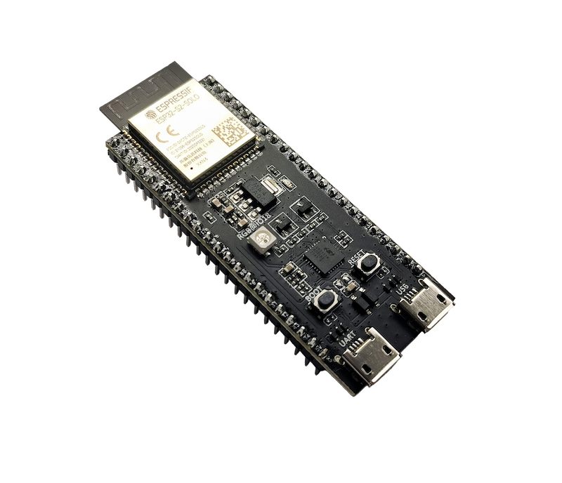
The ESP32-S2-DevKitC-1 is Espressif’s entry-level development board for the ESP32-S2 – a single-core Wi-Fi microcontroller with native USB, 43 GPIOs, ADC, DAC, touch, and a rich set of peripherals.
This guide focuses on pinout and GPIO selection for the DevKitC-1, so you can safely wire sensors, relays and USB without fighting strange boot issues.
Important: This article targets the official ESP32-S2-DevKitC-1 board (with ESP32-S2-SOLO-2 / SOLO-2U modules), as documented by Espressif. Espressif Docs
1. Board overview
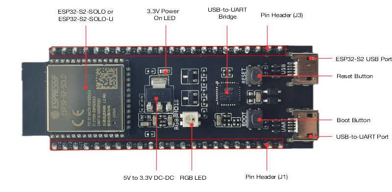
On the DevKitC-1, Espressif breaks out almost all usable GPIOs to the two 22-pin headers (J1 and J3) on the sides of the board. Only the internal SPI flash bus is not exposed.
Key onboard components:
- ESP32-S2-SOLO-2 / SOLO-2U module (8 MB Flash + 2 MB PSRAM, PCB or external antenna)
- Two USB ports
- USB-to-UART port (Micro-USB) – classic serial + power
- Native ESP32-S2 USB port – full-speed USB 1.1 OTG (can act as USB device or host)
- 5 V → 3.3 V LDO regulator
- Reset button (EN / CHIP_PU)
- Boot button (for download mode)
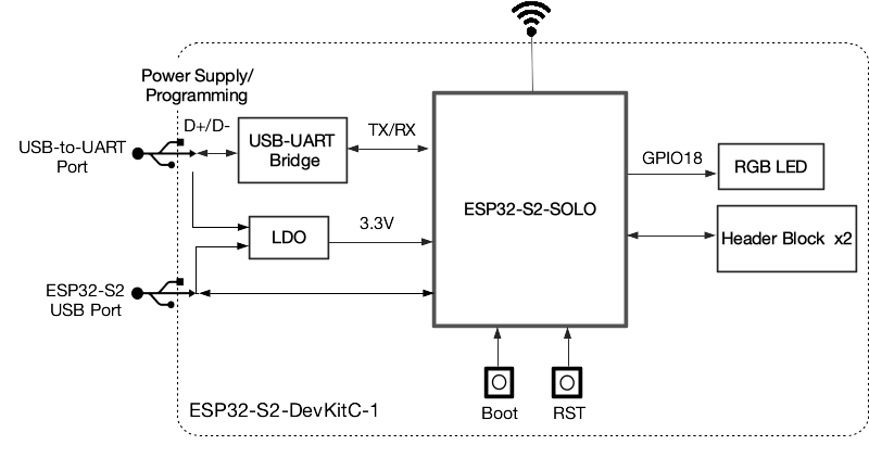
- On-board RGB LED on GPIO18
The board runs at 3.3 V logic – never connect 5 V logic directly to GPIOs.
2. Power supply options
According to Espressif’s hardware reference, there are three mutually exclusive ways to power the DevKitC-1:
- USB-to-UART port (Micro-USB)
- ESP32-S2 USB port (native USB)
- Header pins
- 5V + GND – feed 5 V into the onboard regulator
- 3V3 + GND – feed regulated 3.3 V directly
Practical rules:
- For development → just use the USB-to-UART port (it powers + provides serial).
- If you power from 5V pin, make sure it’s a stable 5 V source (e.g. DC/DC buck from 12 V).
- If you power from 3V3, your regulator must handle peak Wi-Fi current.
3. ESP32-S2 GPIO basics
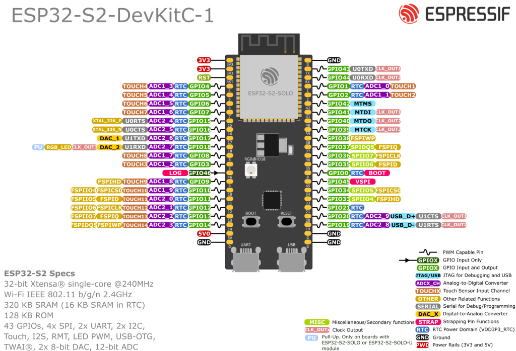
The ESP32-S2 SoC exposes 43 GPIOs (GPIO0-21 and GPIO26-46).
On the DevKitC-1:
- Most GPIOs are broken out to J1/J3.
- Some pins are reserved / “not recommended”:
- GPIO26-32 – usually tied to internal SPI flash / PSRAM
- GPIO39-42 – usually used for JTAG debugging
General rules:
- Logic level: 3.3 V only
- All GPIOs are highly multiplexed – digital I/O, ADC, touch, USB, UART, I²C, SPI, PWM, etc.
4. Strapping pins & “dangerous” pins
The ESP32-S2 has three strapping pins that are sampled at reset to decide boot mode and SPI flash voltage
- GPIO0 – bootloader / normal boot selection
- GPIO45 – selects VDD_SPI voltage (3.3 V vs 1.8 V)
- GPIO46 – controls ROM boot messages & participates in boot mode
Additionally:
- GPIO46 is input-only and has a fixed pulldown.
What this means in practice:
- Avoid driving GPIO0, GPIO45 or GPIO46 with external circuits that strongly pull them high/low at reset – you can:
- Prevent the board from booting
- Misconfigure flash voltage (GPIO45) and risk damaging flash/PSRAM
- Treat GPIO46 as a special input only pin (for e.g. a debug jumper, not a main sensor).
If you must use them, use relatively weak pulls and make sure the reset-time levels are compatible with normal boot.
5. Safe “everyday” GPIOs on DevKitC-1
From Espressif’s header tables (J1/J3) and the chip’s GPIO notes, we can derive a set of “boring and safe” pins for everyday use
5.1 Recommended general-purpose I/O
These are good defaults for digital inputs/outputs, PWM, etc. on DevKitC-1:
- GPIO1, 2, 3, 4, 5, 6, 7, 8, 9, 10
- GPIO11, 12, 13, 14, 15, 16, 17, 18
- GPIO19, 20, 21
- GPIO33, 34, 35, 36, 37, 38
- GPIO43, 44, 45 (45 with boot-time care)
Exceptions / notes:
- GPIO18 drives the on-board RGB LED (WS2812-style) by default. Using it is fine, just be aware of that connection.
- GPIO39-42 – avoid unless you know what you’re doing; often kept for JTAG.
- GPIO26-32 – usually reserved for internal SPI flash/PSRAM on the module; treat them as off-limits unless the specific module says otherwise.
5.2 Input-only pin
- GPIO46 – input-only, strapping pin, fixed pulldown → good for a rarely used configuration jumper, not for outputs.
6. ADC pins (analog inputs)
The ESP32-S2 integrates two 13-bit SAR ADCs with 20 channels:
- ADC1: GPIO 1–10
- ADC2: GPIO 11–20
On ESP32-S2, ADC1 and ADC2 can both be used with Wi-Fi enabled, but the Wi-Fi subsystem has higher priority. In practice this means:
- ADC reads may occasionally fail when Wi-Fi is busy; your code should be prepared to retry.
- Many libraries still recommend ADC1 as the more “predictable” set for Wi-Fi projects.
6.1 Recommended ADC pins on DevKitC-1
Good choices for analog sensors:
- ADC1 (best for Wi-Fi projects)
- GPIO1 → ADC1_CH0
- GPIO2 → ADC1_CH1
- GPIO3 → ADC1_CH2
- GPIO4 → ADC1_CH3
- GPIO5 → ADC1_CH4
- GPIO6 → ADC1_CH5
- GPIO7 → ADC1_CH6
- GPIO8 → ADC1_CH7
- GPIO9 → ADC1_CH8
- GPIO10 → ADC1_CH9
- ADC2 (OK with Wi-Fi, but plan for retries)
- GPIO11–20 → ADC2_CH0–9
Design tips:
- Keep analog inputs in 0–3.3 V range (use resistor dividers).
- Add a small 100 nF capacitor to GND near the pin for noisy signals (potentiometers, LDRs etc.).
7. Touch sensors
ESP32-S2 has 15 capacitive touch pads (TOUCH1–TOUCH14) mapped to GPIOs 1–14 & 3–14/?? – the exact mapping per GPIO is listed in Espressif’s tables (J1/J3 and GPIO reference).
Typical “nice” touch pins on DevKitC-1 (not strapping, easy access):
- GPIO1, 2, 3, 4, 5, 6, 7, 8, 9, 10, 11, 12, 13, 14, 15 – each has a
TOUCHxfunction
(You can pick based on physical location on the header.)
Usage ideas:
- Touch buttons on a front panel (no mechanical switches)
- Wake-up source from deep sleep
In Arduino / ESP-IDF, you read them with functions like touchRead(pin) and configure thresholds for wake-up.
8. USB pins (native USB D+ / D-)
One of the biggest advantages of ESP32-S2 vs classic ESP32 is native USB OTG.
On DevKitC-1, the USB D+ and D- signals are routed to:
- GPIO20 → USB_D+ (also ADC2_CH9, U1CTS, etc.)
- GPIO19 → USB_D- (also ADC2_CH8, U1RTS, etc.)
You also get a dedicated ESP32-S2 USB port on the board that is wired to these pins, plus the classic USB-to-UART port.
Practical points:
- If you use native USB (TinyUSB / ESP-IDF), treat GPIO19/20 as USB pins.
- If your firmware does not use USB, they behave like normal GPIOs/ADC – but be careful not to short them while using the USB connector.
9. I²C pins
Like other ESP32 variants, the S2 can route I²C to almost any GPIO via the IO matrix.
For sanity and consistency across your projects, I recommend the following on DevKitC-1:
| Bus | Recommended pins | Why |
|---|---|---|
| I²C SDA | GPIO8 or GPIO3 | ADC1 capable, general-purpose, no special boot role |
| I²C SCL | GPIO9 or GPIO4 | Same as above |
You can of course choose other pins, but avoid:
- GPIO0 / 45 / 46 (strapping)
- GPIO26-32 (SPI flash/PSRAM bus)
Example in Arduino:
#include <Wire.h>

void setup() {
  Wire.begin(8, 9);  // SDA = GPIO8, SCL = GPIO9
}
10. SPI pins
ESP32-S2 has multiple SPI controllers. One is used internally for flash/PSRAM (on GPIO26–32), and two are normally free for user devices.
Do not use GPIO26–32 on DevKitC-1 for your own SPI devices unless you’re absolutely sure the module variant leaves them free.
Practical “VSPI-like” mapping that works well on DevKitC-1:
| Signal | Recommended GPIO |
|---|---|
| SCK | GPIO36 |
| MISO | GPIO35 |
| MOSI | GPIO34 |
| CS | GPIO33 |
These pins are broken out on J3 and not involved in boot/flash by default.
11. UART / Serial pins
ESP32-S2 has 3 UART controllers, but they can be remapped to various GPIOs.
On the DevKitC-1:
- UART0 (console / flashing)
- TX0 → GPIO43 (“TX” pin on J3)
- RX0 → GPIO44 (“RX” pin on J3)
- UART1 / UART2 can be routed to free pins such as GPIO17/18 or GPIO19/20, depending on your design.
Recommendations:
- Leave GPIO43/44 for USB-to-UART / Serial Monitor.
- For an extra hardware serial (e.g. GPS, RS-485): pick a pair from the “safe GPIOs” (e.g. GPIO17 = TX, GPIO16 = RX) and configure the UART driver accordingly in code.
12. Practical pin recipes for ESP32-S2-DevKitC-1
12.1 Typical Wi-Fi sensor + relay node
A clean setup that avoids trouble:
| Function | Recommended GPIOs | Notes |
|---|---|---|
| I²C SDA | GPIO8 | BME280, OLED etc. |
| I²C SCL | GPIO9 | |
| Relay output | GPIO33 or 34 | Far from strapping pins |
| Extra digital input | GPIO35 or 36 | Button, reed switch |
| Analog sensor input | GPIO1 / 2 / 3 / 4 | ADC1 channels (Wi-Fi-friendly) |
12.2 USB-based gadget (HID / CDC) with status LED
| Function | Recommended GPIOs | Notes |
|---|---|---|
| USB D+ / D- | GPIO20 / GPIO19 | Through native USB connector |
| Status RGB LED | GPIO18 | Onboard WS2812-style LED |
| User button | GPIO1 or GPIO3 | Optional touch + digital input |
13. Summary – S2-specific “rules of thumb”
Compared to a classic ESP32 DevKit, the ESP32-S2-DevKitC-1 has a few important twists:
- No Bluetooth, but native USB OTG – USB on GPIO19/20 via the ESP32-S2 USB port.
- Three strapping pins – GPIO0, GPIO45, GPIO46 – don’t load them heavily at reset.
- GPIO46 is input-only with a fixed pulldown.
- GPIO26-32 are usually reserved for the internal flash/PSRAM bus – leave them alone.
- ADC1 = GPIO1-10, ADC2 = GPIO11-20 – both can operate with Wi-Fi, but ADC1 is still the safest choice.
- Most remaining pins (1-21, 33-38, 43-45) are great general-purpose GPIOs for sensors, relays, I²C, SPI, UART, etc.
If you keep those rules in mind and stick to the “safe” sets above, the ESP32-S2-DevKitC-1 becomes a very friendly board for Wi-Fi sensors, USB gadgets and Home Assistant nodes, without mysterious boot problems.