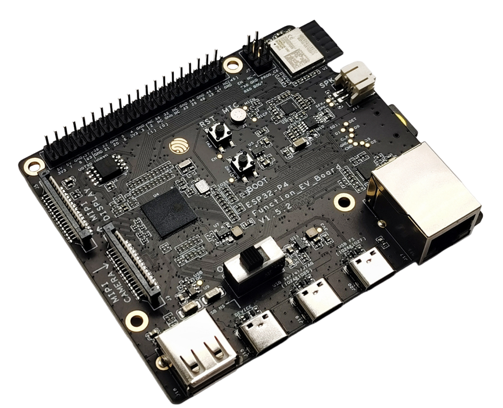
The ESP32-P4-Function-EV-Board v1.5.2 is Espressif’s flagship multimedia dev kit for the ESP32-P4:
- dual-core RISC-V up to ~400 MHz
- up to 32 MB PSRAM + 16 MB flash
- hardware H.264 encoder, MIPI-DSI (LCD), MIPI-CSI (camera), USB 2.0 HS, and Ethernet.
On top of that, the board carries an ESP32-C6-MINI-1 module that provides Wi-Fi 6 + Bluetooth LE connectivity.
All ESP32-P4 GPIOs that Espressif exposes are routed to a 40-pin J1 header at the top edge of the board.
This guide focuses on:
- Understanding the J1 header pinout
- Which pins are “safe” for general use
- Strapping pins and USB-related pins to treat carefully
- Suggested mappings for UART, I²C, SPI, LCD control, etc.
⚠️ All GPIOs are 3.3 V only. Do not feed 5 V into any GPIO pin.
1. Power & USB overview
You can power the board through any of the USB-C ports:
- USB 2.0 OTG HS (Type-C + Type-A; host/device)
- USB Full-Speed port (Type-C)
- USB Serial/JTAG port (Type-C) – recommended for flashing & debugging.
There’s also 3V3 / 5V / GND on the J1 header if you embed the board into a larger system.
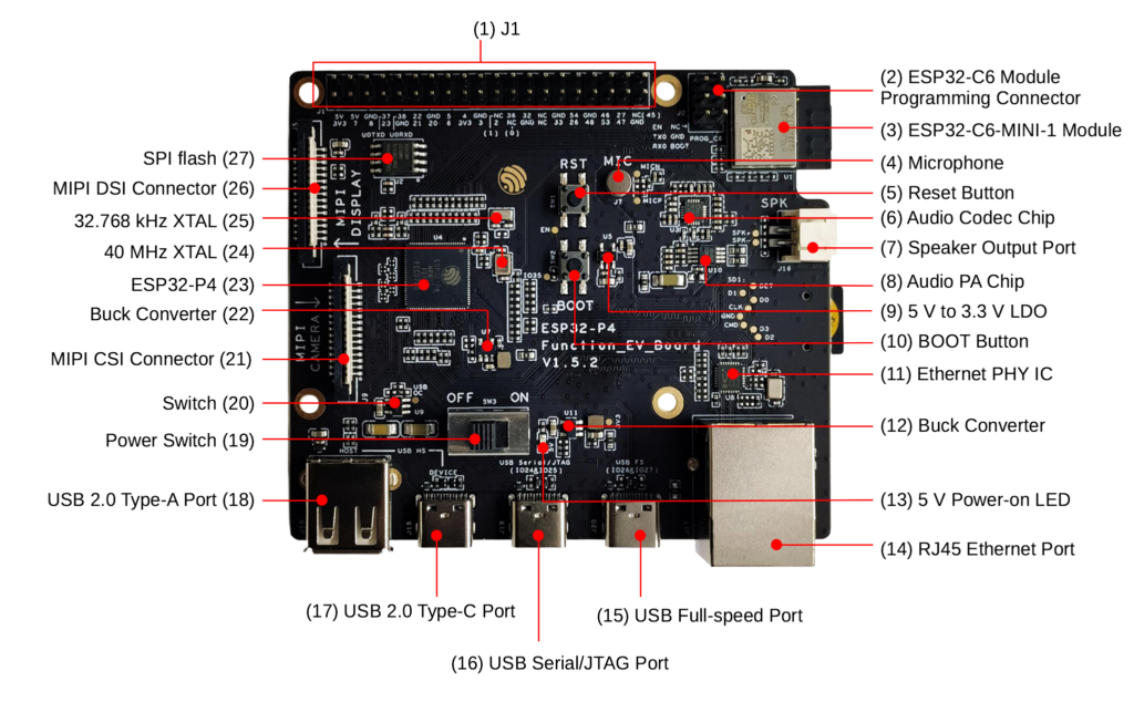
Main on-board blocks:
- ESP32-P4 main MCU
- ESP32-C6-MINI-1 Wi-Fi 6 / BLE module
- RJ45 Ethernet (10/100 Mbps) with PHY
- USB 2.0 OTG: Type-C + Type-A port
- USB Serial/JTAG (FS) for flashing & debugging
- MIPI-DSI (LCD) + MIPI-CSI (camera) FFC connectors
- Audio path: ES8311 codec + NS4150B audio PA + speaker header + mic
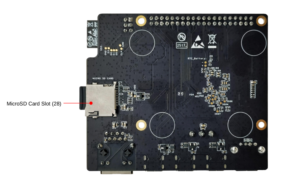
- microSD slot (4-bit mode)
2. J1 header pinout (40-pin)
All the user-accessible GPIOs live on header J1:
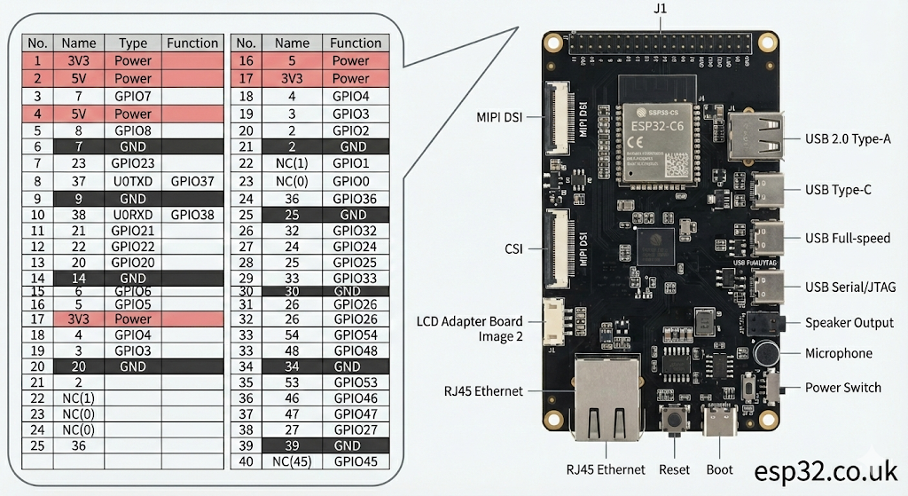
| Pin | Label | Type | Notes |
|---|---|---|---|
| 1 | 3V3 | P | 3.3 V out |
| 2 | 5V | P | 5 V |
| 3 | 7 | GPIO | GPIO7 |
| 4 | 5V | P | 5 V |
| 5 | 8 | GPIO | GPIO8 |
| 6 | GND | P | Ground |
| 7 | 23 | GPIO | GPIO23 |
| 8 | 37 | GPIO | GPIO37, U0TXD (strapping) |
| 9 | GND | P | Ground |
| 10 | 38 | GPIO | GPIO38, U0RXD (strapping) |
| 11 | 21 | GPIO | GPIO21 |
| 12 | 22 | GPIO | GPIO22 |
| 13 | 20 | GPIO | GPIO20 |
| 14 | GND | P | Ground |
| 15 | 6 | GPIO | GPIO6 |
| 16 | 5 | GPIO | GPIO5 |
| 17 | 3V3 | P | 3.3 V out |
| 18 | 4 | GPIO | GPIO4 |
| 19 | 3 | GPIO | GPIO3 |
| 20 | GND | P | Ground |
| 21 | 2 | GPIO | GPIO2 |
| 22 | NC(1) | GPIO | GPIO1 (requires HW mod) |
| 23 | NC(0) | GPIO | GPIO0 (requires HW mod) |
| 24 | 36 | GPIO | GPIO36 (strapping) |
| 25 | GND | P | Ground |
| 26 | 32 | GPIO | GPIO32 |
| 27 | 24 | GPIO | GPIO24 (USB-JTAG default) |
| 28 | 25 | GPIO | GPIO25 (USB-JTAG default) |
| 29 | 33 | GPIO | GPIO33 |
| 30 | GND | P | Ground |
| 31 | 26 | GPIO | GPIO26 (LCD PWM in Espressif examples) |
| 32 | 54 | GPIO | GPIO54 (ADC1_CH13 etc.) |
| 33 | 48 | GPIO | GPIO48 |
| 34 | GND | P | Ground |
| 35 | 53 | GPIO | GPIO53 (ADC1_CH12) |
| 36 | 46 | GPIO | GPIO46 |
| 37 | 47 | GPIO | GPIO47 |
| 38 | 27 | GPIO | GPIO27 (LCD reset in examples) |
| 39 | GND | P | Ground |
| 40 | NC(45) | GPIO | GPIO45 (needs HW mod to free SD_PWRn) |
Notes:
- GPIO0 / GPIO1 / GPIO45 are present but disabled by default on v1.5.2; you must move resistors to re-enable them.
- GPIO24 / GPIO25 are tied to USB-JTAG by default. If you repurpose them, you lose USB-JTAG.
3. Strapping pins and special pins
From the ESP32-P4 docs:
- Strapping pins: GPIO34, GPIO35, GPIO36, GPIO37, GPIO38
On this board, the ones that actually appear on J1 are:
- GPIO36 (J1-24)
- GPIO37 (J1-8, also U0TXD)
- GPIO38 (J1-10, also U0RXD)
Guidelines:
- Don’t hard-pull them to strange levels during reset (no big caps, relays, or heavy loads).
- After boot, they behave like normal GPIOs, but for sanity avoid using 36/37/38 for critical external hardware in beginner designs.
USB-JTAG pins:
- GPIO24 / GPIO25 → used by USB Serial/JTAG.
- If you reassign them as normal GPIOs, you lose USB-JTAG and easy debugging.
High-number ADC pins:
- GPIO41–54 carry ADC1 channels and analog comparator inputs (on the chip).
- This board only exposes GPIO53 and GPIO54 from that group (J1-35, J1-32).
4. “Safe” general-purpose GPIO recommendations
If you just want pins that don’t impact boot, USB-JTAG, or LCD examples, the following J1 pins are good defaults:
GPIO2, 3, 4, 5, 6, 7, 8, 20, 21, 22, 23, 26, 32, 33, 46, 47
Why these?
- Not used by default for USB-JTAG (24/25)
- Not strapping pins (except 37/38/36 which we deliberately skipped)
- Not hard-wired for LCD control in Espressif’s 7″ display examples (they use 26/27 for PWM/RST, but that’s only via a DuPont wire, so it’s optional).
You can still use 26 and 27 safely if you’re not driving the LCD adapter as in Espressif’s reference wiring, or if you plan and document your usage.
5. ADC pins on this board
ESP32-P4 integrates two ADC units with multiple channels.
From the GPIO reference, analog-enabled pins include GPIO41–54, with ADC1 channels 8-13 mapped on GPIO49–54.
On the J1 header we actually get:
- GPIO54 → ADC1_CH13 (J1-32)
- GPIO53 → ADC1_CH12 (J1-35)
So for analog:
Use GPIO53 or GPIO54 for ADC inputs on this board.
Keep the input 0–3.3 V, and add a resistor divider for higher voltages.
6. UART, I²C, SPI suggestions
Because ESP32-P4 has a full GPIO matrix, almost any free pin can host any digital peripheral.
These are sensible defaults that keep things consistent with Espressif docs and common examples.
6.1 Debug UART (UART0)
By default, UART0 is already mapped to:
- TX → GPIO37 (J1-8)
- RX → GPIO38 (J1-10)
If you’re using USB Serial/JTAG for logs, you may not even need the UART0 pins. But if you break them out:
- Don’t add big loads to GPIO37/38, they’re also strapping pins.
6.2 Extra UART (UART1)
For a second serial port (GPS, RS-485, etc.):
- RX = GPIO21 (J1-11)
- TX = GPIO22 (J1-12)
This avoids boot pins and USB-JTAG completely.
6.3 I²C bus
Two simple and safe I²C pairs:
- Option A (my default):
- SDA = GPIO21
- SCL = GPIO22
- Option B (keep 21/22 free for UART):
- SDA = GPIO23
- SCL = GPIO20
Because of the GPIO matrix, you just specify the pins in ESP-IDF:
i2c_config_t conf = {
    .mode = I2C_MODE_MASTER,
    .sda_io_num = GPIO_NUM_21,
    .scl_io_num = GPIO_NUM_22,
    .sda_pullup_en = GPIO_PULLUP_ENABLE,
    .scl_pullup_en = GPIO_PULLUP_ENABLE,
    .master.clk_speed = 400000
};
i2c_param_config(I2C_NUM_0, &conf);
i2c_driver_install(I2C_NUM_0, conf.mode, 0, 0, 0);
6.4 SPI bus
Typical user SPI mapping:
- SCLK → GPIO4
- MOSI → GPIO5
- MISO → GPIO6
- CS → GPIO7 (or 8/20/23 if you need more CS lines)
All of these are low-risk GPIOs on J1 and not tied to USB or boot.
7. LCD & camera connections (high level)
For the 7″ capacitive touch LCD, Espressif’s guide shows:
- LCD uses the MIPI-DSI FFC connector.
- From the LCD adapter board, you manually wire:
- RST_LCD → GPIO27 (J1-38)
- PWM (backlight) → GPIO26 (J1-31)
- Optional 5V / GND if you don’t power LCD via its own USB-C.
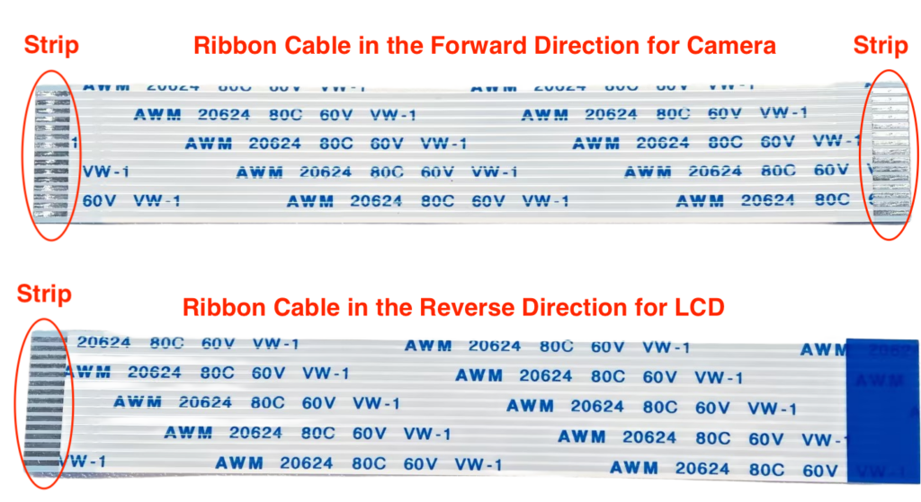
For the 2 MP camera, you simply plug the camera adapter into the MIPI-CSI connector with the “forward” FFC cable; no extra GPIO wiring needed.
So if you are not using the official LCD:
- GPIO26/27 are completely free and perfectly good GPIOs.
8. Ethernet, microSD, audio – what not to reuse
Some ESP32-P4 pins are wired internally to board peripherals:
- Ethernet PHY – uses a chunk of GPIOs for RMII; these are not on J1, so don’t worry about them.
- microSD slot, audio codec, and camera/LCD use dedicated pins and the FFC connectors; again, most of these signals are not on J1 and won’t clash with your own wiring.
If you need to know exact internal mappings (for very advanced use), check the schematic PDF from Espressif.
9. Quick cheat sheet
Good, generic GPIOs (low drama):
2, 3, 4, 5, 6, 7, 8, 20, 21, 22, 23, 26, 32, 33, 46, 47
Boot-sensitive (strapping) on J1:
36, 37, 38
USB-JTAG pins:
24, 25 (avoid if you want easy debugging)
ADC inputs exposed on J1:
53, 54
Nice defaults:
- I²C0 → SDA 21, SCL 22
- SPI → SCLK 4, MOSI 5, MISO 6, CS 7
- Extra UART → RX 21, TX 22
- LCD control (if using Espressif LCD kit) → RST 27, PWM 26