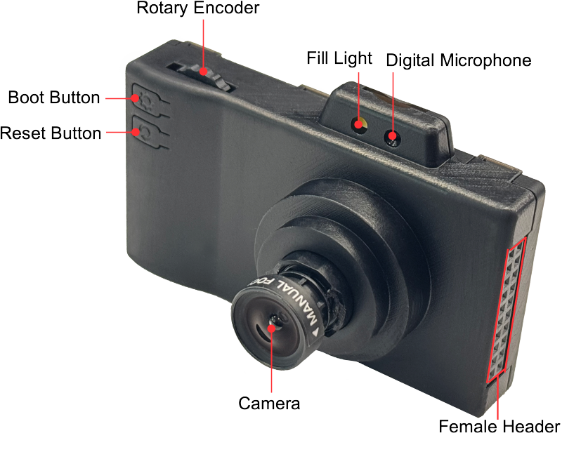
The ESP32-P4-EYE is one of Espressif’s newest dev kits: a tiny “camera-in-a-box” based on the ESP32-P4 SoC, with a built-in LCD, 2 MP camera, microphone, MicroSD and dual USB-C ports. It’s designed as a ready-made platform for AI vision and audio projects.
Unlike the usual DevKitC boards, the P4-EYE hides most of the hardware inside a plastic enclosure, but it still exposes a 2×10 female header so you can add your own sensors and actuators.
This guide gives you a practical overview of:
- What’s on the board
- How power & USB work
- How the 2×10 header fits into the picture
- Which pins are “safe” to use and which ones are tied to on-board peripherals
⚠️ Important: Espressif don’t provide a text pin table for the 2×10 header in the user guide – only a schematic/PCB PDF. For exact per-pin mapping, always cross-check your board revision against the official schematic in the docs.
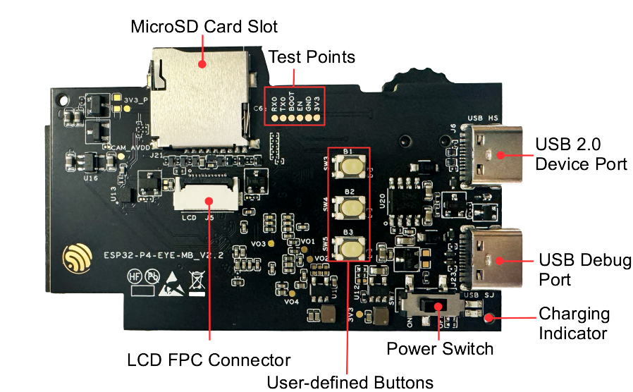
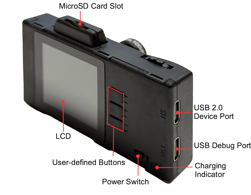
1. Board overview
On the front/top PCB you have:
- 1.54″ SPI LCD (240×240, ST7789 controller – backlight on
LCD_BL= GPIO20) - MIPI-CSI camera (2 MP, OV2710 sensor)
- MicroSD slot (4-line SDIO / SDIO 3.0, can also be used via SPI)
- Two USB-C ports
USB 2.0– High-Speed USB device (connected to ESP32-P4 HS OTG)Debug– Full-Speed USB-Serial/JTAG + power
- User buttons (3× side buttons, free for your own UI)
- Power switch and charge indicator LED
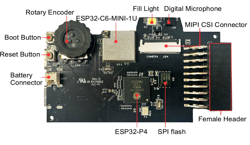
On the back PCB you have:
- ESP32-P4 SoC (dual-core RISC-V, with 16 MB SPI flash + up to 32 MB PSRAM)
- ESP32-C6-MINI-1U module for Wi-Fi 6 / BLE / 802.15.4 radio offload
- Digital microphone (PDM)
- Fill light LED
- Rotary encoder (for menu navigation / zoom, etc.)
- MIPI-CSI connector for the camera ribbon
- The 2×10 female header for extra GPIO
2. Power options
You can power ESP32-P4-EYE in three ways:
- USB 2.0 Device port (HS)
- USB-C, marked USB 2.0 on the case
- Powers the board and gives you a High-Speed USB device interface
- Typical for mass-storage / UVC / custom USB experiments
- USB Debug port (FS)
- USB-C, marked Debug
- Recommended for firmware flashing and serial debugging
- Provides power + USB-Serial-JTAG
- Battery connector (inside the case)
- Small JST-style connector on the PCB
- 1-cell Li-ion/LiPo pack (≤ 4 mm × 25 mm × 45 mm)
- Battery is charged automatically when USB is plugged in
For most dev work, you’ll simply: plug a USB-C cable into the Debug port and flash from ESP-IDF.
3. The 2×10 female header
ESP32-P4-EYE exposes a 2×10 female header (20 pins total) on the PCB back. The user guide describes it simply as a:
“2 × 10P header, customizable based on application.”
Internally, this header carries:
- 3V3 / 5V power and GND
- Several ESP32-P4 GPIOs with full functionality (ADC, PWM, I²C, SPI, etc.)
- Some signals associated with MIPI-CSI and other high-speed blocks (not recommended for random reuse)
Because there is no official text table of the header pins, you should always:
- Download the ESP32-P4-EYE schematic (linked in the docs as
ESP32-P4-EYE Schematic.pdf) - Locate the female header symbol (usually
J1/J2or “Female Header”) - Identify which ESP32-P4 pins are routed there
4. On-board peripherals & reserved pins
Even without the exact header map, we know which ESP32-P4 pins are dedicated to on-board peripherals from the user guide + datasheets:
You should not reuse these pins unless you really know what you’re doing:
- LCD (SPI + backlight)
- ST7789 display
- Backlight control:
LCD_BL= GPIO20 (documented) - Other LCD SPI pins (SCK, MOSI, DC, CS, RST) are also dedicated – see schematic
- Camera (MIPI-CSI)
- Uses a MIPI CSI lane pair + control lines (CLK, HS/LP lanes)
- These pins are high-speed and not for general I/O
- MicroSD slot
- 4-bit SDIO: CMD, CLK, D0–D3
- May be shared with SPI in some configurations
- USB 2.0 HS device
- Uses a dedicated USB PHY interface (not re-routable as GPIO)
- Microphone (DMIC)
- Uses PDM clock/data pins from the ESP32-P4
- Rotary encoder & buttons
- Connected to GPIOs used in the factory firmware for UI
- ESP32-C6-MINI-1U
- Is connected to the ESP32-P4 via SDIO/UART (for Wi-Fi/BLE), plus its own antenna, etc.
5. “Safe” GPIO usage strategy
Because ESP32-P4-EYE is so packed, the safest approach is:
- Scan the header pins in the schematic and mark:
- Power pins:
3V3,5V,GND - Pure GPIO signals not labelled with LCD, CAM, SD, USB, MIC, ENC, etc.
- Power pins:
- Treat those pure GPIOs as general-purpose “safe” pins for:
- Digital I/O
- PWM (LEDs, small servos)
- I²C / SPI / UART (as long as they are not already assigned)
- Avoid reusing any GPIO with labels like
LCD_*,CAM_*,SD_*,USB_*,PDM_*,ENC_*.
| Category | Recommendation on ESP32-P4-EYE |
|---|---|
| Power | Use 3V3 from header for sensors; 5V only for modules that need it. |
| Ground | Several GND pins on the header – use any close to your signal. |
| Digital I/O | Use GPIOs not tagged as LCD, CAM, SD, USB, MIC, ENC in the schematic. |
| I²C | Pick any two free GPIOs as SDA/SCL and configure with gpio_num in code. |
| SPI | Same: choose free GPIOs for SCK, MOSI, MISO, CS. |
| UART | Any free GPIO can be mapped to TX/RX using the IO-mux in ESP-IDF. |
| PWM | Most free GPIOs support LEDC PWM timers. |
| ADC | Use GPIOs that are part of ESP32-P4 analog-capable set and not used by board peripherals (from SoC datasheet + schematic). |
6. Example: controlling the LCD backlight (GPIO20)
One pin we do know by name from the user guide is the LCD backlight:
“ESP32-P4-EYE features the ST7789 display, which uses the
LCD_BLpin (GPIO20) to control the backlight.”
Minimal ESP-IDF snippet (C) to fade the backlight with PWM:
#include "driver/ledc.h"
#include "esp_log.h"

#define LCD_BL_GPIO 20

void lcd_backlight_init(void)
{
    // Configure LEDC for PWM on GPIO20
    ledc_timer_config_t timer = {
        .speed_mode       = LEDC_LOW_SPEED_MODE,
        .timer_num        = LEDC_TIMER_0,
        .duty_resolution  = LEDC_TIMER_10_BIT, // 0–1023
        .freq_hz          = 5000,
        .clk_cfg          = LEDC_AUTO_CLK
    };
    ledc_timer_config(&timer);

    ledc_channel_config_t ch = {
        .gpio_num       = LCD_BL_GPIO,
        .speed_mode     = LEDC_LOW_SPEED_MODE,
        .channel        = LEDC_CHANNEL_0,
        .timer_sel      = LEDC_TIMER_0,
        .duty           = 0,
        .hpoint         = 0
    };
    ledc_channel_config(&ch);
}

void lcd_backlight_set_percent(uint8_t percent)
{
    if (percent > 100) percent = 100;
    uint32_t duty = (1023 * percent) / 100;
    ledc_set_duty(LEDC_LOW_SPEED_MODE, LEDC_CHANNEL_0, duty);
    ledc_update_duty(LEDC_LOW_SPEED_MODE, LEDC_CHANNEL_0);
}
Use it like:
lcd_backlight_init();
lcd_backlight_set_percent(100); // full brightness
7. Getting started with software
- Install ESP-IDF (v5.5 or newer) using the official installer or
idf.pysetup. - Clone the esp-dev-kits repo and check out the
release/v5.5branch examples foresp32-p4-eye. - Build and flash the factory example:
idf.py set-target esp32p4 idf.py menuconfig # optional board-specific settings idf.py flash monitor - The stock demo gives you:
- Camera preview
- Photo capture / timer capture
- Video recording to SD card
- On-screen settings (resolution, saturation, contrast, etc.)