Quick Summary :
This beginner guide explains the famous Blink sketch line-by-line on an ESP32/Arduino board. You’ll learn what setup() and loop() do, how pinMode() works, what HIGH/LOW really mean, and why delay(1000) makes the LED blink once per second (plus fixes if your board’s LED is on a different pin).
If you’re brand new to Arduino/ESP32, Blink is the first program you should understand. Not because it’s exciting — but because it teaches the 4 things you’ll use forever:
- What setup() does
- What loop() does
- How to set a pin as an output
- How to turn something ON/OFF with code
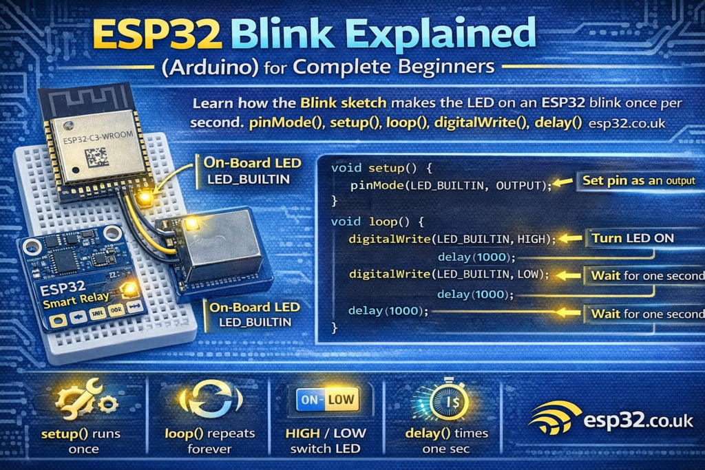
Here’s the Blink sketch:
void setup() {
  // initialize digital pin LED_BUILTIN as an output.
  pinMode(LED_BUILTIN, OUTPUT);
}// the loop function runs over and over again forever
void loop() {
  digitalWrite(LED_BUILTIN, HIGH);  // change state of the LED by setting the pin to the HIGH voltage level
  delay(1000);                      // wait for a second
  digitalWrite(LED_BUILTIN, LOW);   // change state of the LED by setting the pin to the LOW voltage level
  delay(1000);                      // wait for a second
}
1) What is LED_BUILTIN?
LED_BUILTIN is a name (a constant) that Arduino defines for “the pin that controls the on-board LED”.
- On many Arduino boards it’s pin 13
- On ESP32 boards it’s often pin 2
- On some ESP32 boards, the LED might be on a different pin, or not present at all.
So this line:
pinMode(LED_BUILTIN, OUTPUT);
means:
✅ “Whatever pin the board uses for its built-in LED, I want to control it as an output.”
2) What does setup() do?
setup() runs once when the ESP32 starts:
- when you press reset
- when you plug it in
- when you upload a new program
This is where you put “one-time” setup tasks, like:
- setting pin modes
- starting Serial (Serial Monitor)
- connecting to Wi-Fi
- initializing sensors
In your code:
void setup() {
  pinMode(LED_BUILTIN, OUTPUT);
}
This tells the ESP32:
✅ “I will use this pin to send a signal out (to control the LED).”
3) What does loop() do?
After setup() finishes, Arduino runs loop() again and again forever.
Think of it like:
- setup = “prepare the hardware”
- loop = “keep doing your program logic repeatedly”
Your loop() turns the LED on, waits, turns it off, waits, and repeats.
4) What does pinMode(pin, OUTPUT) mean?
Pins can be used in different ways:
- INPUT → read something (button, sensor signal)
- OUTPUT → control something (LED, relay, buzzer)
- INPUT_PULLUP → input but with an internal pull-up resistor
So:
pinMode(LED_BUILTIN, OUTPUT);
means:
✅ “This pin will drive voltage out to control the LED.”
Without this, digitalWrite() might not behave reliably.
5) What does digitalWrite(pin, HIGH/LOW) do?
This is where the LED is controlled:
Turn LED ON
digitalWrite(LED_BUILTIN, HIGH);
This sets the pin to HIGH, which usually means 3.3V on ESP32.
If the LED is wired in the “normal” way, HIGH turns it ON.
Turn LED OFF
digitalWrite(LED_BUILTIN, LOW);
This sets the pin to LOW (0V), which turns it OFF.
Important: Some boards have an LED wired “active-low”, meaning HIGH = off and LOW = on. If your blink looks inverted, that’s why.
6) What does delay(1000) do?
delay(1000) pauses the program for 1000 milliseconds.
- 1000 ms = 1 second
So your loop is:
- LED ON
- wait 1 second
- LED OFF
- wait 1 second
- repeat forever
This is why it blinks at a steady pace.
7) The program in plain English
Here’s your code translated to human language:
- When the ESP32 starts:
- Set the built-in LED pin as an output.
- Then forever:
- Turn the LED on.
- Wait 1 second.
- Turn the LED off.
- Wait 1 second.
That’s it.
8) Common beginner problems
“My ESP32 doesn’t blink”
Possible reasons:
- Your board doesn’t have a built-in LED
LED_BUILTINisn’t defined for your board package- The LED is on a different GPIO than expected
Fix: try this on many ESP32 boards:
#define LED_PIN 2void setup() {
  pinMode(LED_PIN, OUTPUT);
}void loop() {
  digitalWrite(LED_PIN, HIGH);
  delay(1000);
  digitalWrite(LED_PIN, LOW);
  delay(1000);
}
If GPIO2 doesn’t work, try GPIO4 or check your board’s pinout.
“My LED blinks backwards”
Your LED might be active-low. Flip HIGH/LOW:
digitalWrite(LED_BUILTIN, LOW);  // ON (active-low)
delay(1000);
digitalWrite(LED_BUILTIN, HIGH); // OFF
delay(1000);
9) Next step: blink faster, blink patterns
Once you understand Blink, you’re ready for:
- changing the delay to make it faster/slower
- blinking patterns (SOS, double blink, heartbeat)
- blinking based on a button press
- blinking when Wi-Fi connects