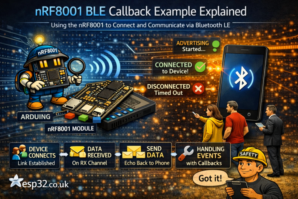
This example shows how to use the Adafruit nRF8001 Bluetooth Low Energy breakout in callback mode. The sketch starts advertising, reports connection events over Serial, receives incoming BLE UART data, prints it, and immediately echoes the same data back to the sender.
The nice thing about this example is that almost all the logic is event-driven. Instead of constantly checking for incoming data in the main loop, the sketch uses callbacks for both BLE state changes and received data. That makes the code cleaner and easier to understand.
What this example does
This sketch turns the nRF8001 module into a simple BLE UART echo device.
In practice it does the following:
- Starts the BLE radio and begins advertising
- Prints connection status messages to the Serial Monitor
- Waits for incoming data over the BLE UART service
- Prints the received text and hex values
- Sends the exact same data back to the connected device
So if you send text from a phone app or another compatible BLE UART client, the board will receive it and echo it back.
Libraries used
The example uses:
SPI.hAdafruit_BLE_UART.h
SPI.h is needed because the nRF8001 breakout communicates with the microcontroller over SPI.
Adafruit_BLE_UART.h is the Adafruit library that handles the BLE UART functionality and ACI event handling for the nRF8001.
Pin definitions
The code defines three control pins:
#define ADAFRUITBLE_REQ 10
#define ADAFRUITBLE_RDY 2
#define ADAFRUITBLE_RST 9
These are used to communicate with the nRF8001 module:
REQis the request lineRDYis the ready lineRSTis the reset line
Then the sketch creates the BLE UART object:
Adafruit_BLE_UART uart = Adafruit_BLE_UART(ADAFRUITBLE_REQ, ADAFRUITBLE_RDY, ADAFRUITBLE_RST);
This object is what the rest of the sketch uses to control the module.
Why this version is different
The comment near the top explains the main idea:
This version uses callbacks on the event and RX so there’s no data handling in the main loop.
That is the key point of the whole example.
Instead of writing all BLE handling directly inside loop(), the sketch registers two callback functions:
- one for BLE events
- one for received data
That makes the main loop extremely small and keeps the real logic in dedicated functions.
The ACI event callback
This function handles BLE state changes:
void aciCallback(aci_evt_opcode_t event)
It is called automatically whenever important ACI events happen.
Inside the switch, the sketch handles three main cases:
ACI_EVT_DEVICE_STARTEDACI_EVT_CONNECTEDACI_EVT_DISCONNECTED
ACI_EVT_DEVICE_STARTED
When the device starts up, the sketch prints:
Serial.println(F("Advertising started"));
This tells you the module is alive and has started advertising so other BLE devices can discover it.
ACI_EVT_CONNECTED
When a BLE connection is made, it prints:
Serial.println(F("Connected!"));
That confirms a phone, tablet, or other central device has connected.
ACI_EVT_DISCONNECTED
When the connection ends, or advertising times out, it prints:
Serial.println(F("Disconnected or advertising timed out"));
This is useful because it tells you the device is no longer actively connected.
The RX callback
This function runs whenever data arrives over BLE:
void rxCallback(uint8_t *buffer, uint8_t len)
It receives:
- a pointer to the incoming data buffer
- the number of bytes received
Printing the incoming data
First, the sketch prints how many bytes arrived:
Serial.print(F("Received "));
Serial.print(len);
Serial.print(F(" bytes: "));
Then it loops through the buffer and prints each byte as a character:
for(int i=0; i<len; i++)
  Serial.print((char)buffer[i]);
So if the remote device sends Hello, the Serial Monitor will show that text.
Printing the hex values
After that, the code prints the same bytes again in hexadecimal form:
for(int i=0; i<len; i++)
{
  Serial.print(" 0x");
  Serial.print((char)buffer[i], HEX);
}
That is useful for debugging because sometimes incoming data may include non-printable characters or raw binary values.
Echoing the data back
At the end of the callback, the sketch sends the same bytes back:
uart.write(buffer, len);
That is why this is called an echo demo. Whatever the remote device sends gets transmitted straight back.
What happens in setup()
The setup() function prepares Serial output and starts the BLE module.
Serial initialization
Serial.begin(9600);
while(!Serial);
The while(!Serial); line is there for boards like the Leonardo or Micro, where the sketch may wait for the USB Serial connection to become ready before continuing.
Then the sketch prints a startup message:
Serial.println(F("Adafruit Bluefruit Low Energy nRF8001 Callback Echo demo"));
Registering the callbacks
Next, the sketch attaches the two callback functions:
uart.setRXcallback(rxCallback);
uart.setACIcallback(aciCallback);
This tells the library which functions to call when data arrives or when BLE events occur.
Optional device name
There is also this commented line:
// uart.setDeviceName("NEWNAME"); /* 7 characters max! */
That means you can change the BLE device name, but the name length is limited.
Starting BLE
Finally:
uart.begin();
This initializes the module and starts the BLE process.
What happens in loop()
The loop() function is only one line:
uart.pollACI();
This is important. Even though the sketch uses callbacks, it still needs to continuously poll the ACI interface so the library can process events and trigger those callbacks.
So the loop is simple, but it is still essential.
What you should see in Serial Monitor
When everything is working, the Serial Monitor will show messages like:
Adafruit Bluefruit Low Energy nRF8001 Callback Echo demoAdvertising startedConnected!Received 5 bytes: Hello [ 0x48 0x65 0x6C 0x6C 0x6F ]Disconnected or advertising timed out
That makes this example very good for basic BLE troubleshooting.
Why this example is useful
This sketch is a good learning example because it demonstrates several important ideas at once:
- BLE advertising
- BLE connection events
- receiving UART-style BLE data
- using callbacks instead of handling everything in the main loop
- echoing data back for quick testing
If you are trying to understand how event-driven BLE code works, this example is much cleaner than a sketch that mixes everything together in one big loop.
Important practical notes
A few things are worth keeping in mind:
- This is an echo demo, not a full application protocol
- The sketch depends on regular
uart.pollACI()calls in the loop - Incoming data is printed both as text and as hex for easier debugging
- The callback approach keeps the structure clean and scalable
- The optional device name has a short length limit
Final thoughts
The Adafruit nRF8001 callback echo example is a simple but very effective demo. It shows how to react to BLE events properly, how to receive data without cluttering the main loop, and how to send a response back immediately.
For beginners, it is a nice introduction to BLE UART concepts. For more advanced users, it is a solid reminder that callback-based code is often much easier to maintain than constantly checking flags and buffers manually.
|
1 2 3 4 5 6 7 8 9 10 11 12 13 14 15 16 17 18 19 20 21 22 23 24 25 26 27 28 29 30 31 32 33 34 35 36 37 38 39 40 41 42 43 44 45 46 47 48 49 50 51 52 53 54 55 56 57 58 59 60 61 62 63 64 65 66 67 68 69 70 71 72 73 74 75 76 77 78 79 80 81 82 83 84 85 86 87 88 89 90 91 92 93 94 95 96 97 98 99 100 101 102 |
/********************************************************************* This is an example for our nRF8001 Bluetooth Low Energy Breakout Pick one up today in the adafruit shop! ------> http://www.adafruit.com/products/1697 Adafruit invests time and resources providing this open source code, please support Adafruit and open-source hardware by purchasing products from Adafruit! Written by Kevin Townsend/KTOWN for Adafruit Industries. MIT license, check LICENSE for more information All text above, and the splash screen below must be included in any redistribution *********************************************************************/ // This version uses call-backs on the event and RX so there's no data handling in the main loop! #include <SPI.h> #include "Adafruit_BLE_UART.h" #define ADAFRUITBLE_REQ 10 #define ADAFRUITBLE_RDY 2 #define ADAFRUITBLE_RST 9 Adafruit_BLE_UART uart = Adafruit_BLE_UART(ADAFRUITBLE_REQ, ADAFRUITBLE_RDY, ADAFRUITBLE_RST); /**************************************************************************/ /*! This function is called whenever select ACI events happen */ /**************************************************************************/ void aciCallback(aci_evt_opcode_t event) { switch(event) { case ACI_EVT_DEVICE_STARTED: Serial.println(F("Advertising started")); break; case ACI_EVT_CONNECTED: Serial.println(F("Connected!")); break; case ACI_EVT_DISCONNECTED: Serial.println(F("Disconnected or advertising timed out")); break; default: break; } } /**************************************************************************/ /*! This function is called whenever data arrives on the RX channel */ /**************************************************************************/ void rxCallback(uint8_t *buffer, uint8_t len) { Serial.print(F("Received ")); Serial.print(len); Serial.print(F(" bytes: ")); for(int i=0; i<len; i++) Serial.print((char)buffer[i]); Serial.print(F(" [")); for(int i=0; i<len; i++) { Serial.print(" 0x"); Serial.print((char)buffer[i], HEX); } Serial.println(F(" ]")); /* Echo the same data back! */ uart.write(buffer, len); } /**************************************************************************/ /*! Configure the Arduino and start advertising with the radio */ /**************************************************************************/ void setup(void) { Serial.begin(9600); while(!Serial); // Leonardo/Micro should wait for serial init Serial.println(F("Adafruit Bluefruit Low Energy nRF8001 Callback Echo demo")); uart.setRXcallback(rxCallback); uart.setACIcallback(aciCallback); // uart.setDeviceName("NEWNAME"); /* 7 characters max! */ uart.begin(); } /**************************************************************************/ /*! Constantly checks for new events on the nRF8001 */ /**************************************************************************/ void loop() { uart.pollACI(); } |