(Safe Pins, ADC, I²C, SPI, USB, RGB LED)
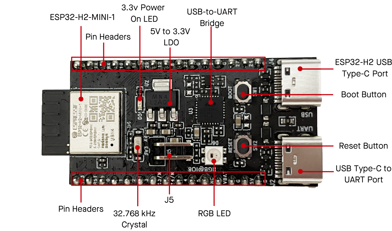
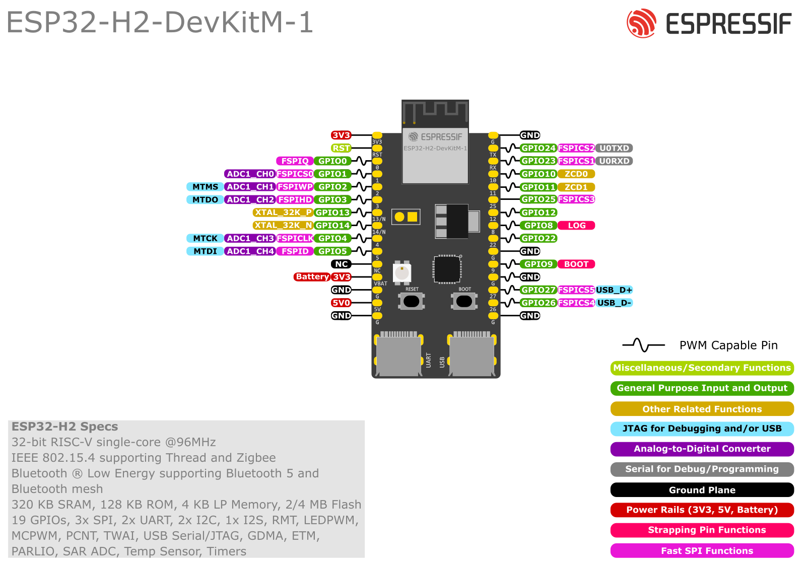
The ESP32-H2-DevKitM-1 is Espressif’s low-power Bluetooth LE + 802.15.4 (Zigbee/Thread/Matter) dev board based on the ESP32-H2-MINI-1/1U module. It’s basically an “ESP32 without Wi-Fi” but with full BLE + Zigbee/Matter support and 4 MB in-package flash.
Most GPIOs are broken out to two 15-pin headers (J1/J3) on the sides, making it breadboard-friendly and perfect for Thread/Zigbee border routers, battery-powered sensors, and Matter bridges.
1. Board overview
Key hardware blocks:
- SoC / module: ESP32-H2 inside ESP32-H2-MINI-1 or MINI-1U
- Radio: Bluetooth 5 LE + IEEE 802.15.4 (Zigbee, Thread, Matter)
- Flash: 4 MB integrated in package
- Power:
- USB-C (USB-UART) – default power
- 5V / GND header
- 3V3 / GND header
- VBAT pin for external 3.3 V / battery
- Connectivity:
- USB-C (native ESP32-H2 USB 2.0 FS)
- USB-C (USB-to-UART bridge)
- On-board peripherals:
- RGB LED on GPIO8
- Power LED
- BOOT and RESET buttons
- J5 jumper for current measurement
All I/O is 3.3 V only – no 5 V tolerance.
2. Power options
From the official user guide:
You can power the board in exactly one of these ways:
- USB-C → USB-UART (default)
- 5V + GND header pins
- 3V3 + GND header pins
Plus:
- VBAT (J1-12) – 3.3 V or battery input for the module’s 3.3 V domain.
- J5 shunt – remove the jumper and insert an ammeter to measure module current only.
For development, just plug the USB-UART Type-C and leave J5 as shipped.
3. J1 and J3 pinout
3.1 J1 header (left side)
From the Espressif header table:
| No. | Name | Type | Function (short) |
|---|---|---|---|
| 1 | 3V3 | P | 3.3 V power |
| 2 | RST | I | EN / reset (high = enable, low = power-off) |
| 3 | 0 | I/O/T | GPIO0, FSPIQ |
| 4 | 1 | I/O/T | GPIO1, FSPICS0, ADC1_CH0 |
| 5 | 2 | I/O/T | GPIO2, FSPIWP, ADC1_CH1, MTMS |
| 6 | 3 | I/O/T | GPIO3, FSPIHD, ADC1_CH2, MTDO |
| 7 | 13/N | I/O/T | GPIO13, XTAL_32K_P (LP crystal, if fitted) |
| 8 | 14/N | I/O/T | GPIO14, XTAL_32K_N (LP crystal, if fitted) |
| 9 | 4 | I/O/T | GPIO4, FSPICLK, ADC1_CH3, MTCK |
| 10 | 5 | I/O/T | GPIO5, FSPID, ADC1_CH4, MTDI |
| 11 | NC | – | Not connected |
| 12 | VBAT | P | 3.3 V supply / battery to module |
| 13 | G | P | Ground |
| 14 | 5V | P | 5 V power input |
| 15 | G | P | Ground |
Notes:
- GPIO13 / GPIO14 cannot be reused if they’re wired to the 32.768 kHz crystal on your board revision.
3.2 J3 header (right side)
| No. | Name | Type | Function |
|---|---|---|---|
| 1 | G | P | Ground |
| 2 | TX | I/O/T | GPIO24, FSPICS2, U0TXD (USB-UART TX) |
| 3 | RX | I/O/T | GPIO23, FSPICS1, U0RXD (USB-UART RX) |
| 4 | 10 | I/O/T | GPIO10, ZCD0 |
| 5 | 11 | I/O/T | GPIO11, ZCD1 |
| 6 | 25 | I/O/T | GPIO25, FSPICS3, strapping |
| 7 | 12 | I/O/T | GPIO12 |
| 8 | 8 | I/O/T | GPIO8, LOG, RGB LED data |
| 9 | 22 | I/O/T | GPIO22 |
| 10 | G | P | Ground |
| 11 | 9 | I/O/T | GPIO9, BOOT, strapping |
| 12 | G | P | Ground |
| 13 | 27 | I/O/T | GPIO27, FSPICS5, USB_D+ |
| 14 | 26 | I/O/T | GPIO26, FSPICS4, USB_D− |
| 15 | G | P | Ground |
So in total you get 19 usable GPIOs: 0–5, 8–14, 22–27.
4. Strapping pins (boot-sensitive)
From the ESP32-H2 GPIO docs:
Strapping pins on ESP32-H2:
GPIO2, GPIO3, GPIO8, GPIO9, GPIO25
What they do:
- GPIO8 & GPIO9 – control boot mode and ROM logging.
- GPIO2 & GPIO3 – participate in some boot / configuration straps.
- GPIO25 – also a strapping pin.
Practical rules:
- Don’t force these pins high/low with big loads or strong external pull-ups/downs during reset.
- Avoid adding big capacitors or relays directly on them.
- After boot they behave as normal GPIOs, but for beginner-friendly projects it’s easier to:
- Treat GPIO2, 3, 8, 9, 25 as “advanced only”.
On this board specifically:
- GPIO8 is already used to drive the RGB LED – the circuit is designed not to break boot.
- GPIO9 is also wired to the BOOT button.
5. “Safe” GPIOs for general use
If you just want pins that never fight with USB, boot, or crystals, a good “safe” set on this board is:
GPIO0, 1, 4, 5, 10, 11, 12, 13, 14, 22, 23, 24**
* Only if your board revision does not use 13/14 for the 32 kHz crystal (on newer boards, they often are used – check silkscreen or schematic).
Pins to treat with care:
- GPIO2, 3, 8, 9, 25 – strapping pins.
- GPIO26 (USB_D−), GPIO27 (USB_D+) – default USB Serial/JTAG; only repurpose if you’re not using USB.
6. ADC pins (analog inputs)
From the header table, ADC functions are mapped to:
- GPIO1 → ADC1_CH0
- GPIO2 → ADC1_CH1
- GPIO3 → ADC1_CH2
- GPIO4 → ADC1_CH3
- GPIO5 → ADC1_CH4
So the board exposes 5 analog channels: GPIO1–5.
Tips:
- Keep input ≤ 3.3 V – use a resistor divider for higher voltages.
- For simple projects, prefer GPIO1, 4, 5 (avoid strapping pins 2/3 if you’re paranoid about boot).
7. USB & Serial (UART)
The DevKitM-1 has two USB-C ports:
- USB-C: ESP32-H2 USB (native)
- Directly connected to GPIO27 (USB_D+) and GPIO26 (USB_D−).
- USB 2.0 full-speed (12 Mbps) with USB Serial/JTAG, CDC, etc.
- USB-C: USB-to-UART
- Connects a bridge chip to GPIO24 (TX) and GPIO23 (RX).
- This is the classic
Serialused by the Arduino core and for flashing.
Recommendations:
- Keep GPIO23/24 for UART0 to make flashing and Serial Monitor painless.
- Treat GPIO26/27 primarily as USB pins; don’t hang random sensors on them unless you know what you’re doing and have disabled USB.
8. On-board RGB LED (GPIO8)
There is an addressable RGB LED (WS2812-style) driven by GPIO8:
- Data in on GPIO8 only.
- Great for status indication (connected, error, commissioning mode, etc.).
Example (Arduino):
#include <Adafruit_NeoPixel.h>

#define LED_PIN   8
#define LED_COUNT 1

Adafruit_NeoPixel rgb(LED_COUNT, LED_PIN, NEO_GRB + NEO_KHZ800);

void setup() {
  rgb.begin();
  rgb.show(); // turn off
}

void loop() {
  rgb.setPixelColor(0, rgb.Color(0, 255, 0)); // green
  rgb.show();
  delay(300);

  rgb.clear();
  rgb.show();
  delay(300);
}
9. I²C pins
Like other ESP chips, ESP32-H2 has a GPIO matrix: I²C can be placed on many pins.
On this board, nice I²C combos that don’t clash with USB/boot:
Option A (simple, digital-only pins)
- SDA = GPIO12 (J3-7)
- SCL = GPIO22 (J3-9)
Option B (if you want ADC + I²C close together)
- SDA = GPIO4 (ADC1_CH3)
- SCL = GPIO5 (ADC1_CH4)
Example (Arduino):
#include <Wire.h>

void setup() {
  Wire.begin(12, 22);  // SDA=12, SCL=22
  Serial.begin(115200);
  Serial.println("I2C started on GPIO12 (SDA) / GPIO22 (SCL)");
}

void loop() {}
Avoid using 2, 3, 8, 9, 25 as your primary I²C signals unless you’re comfortable with strapping behaviour.
10. SPI pins
The “FSPI” alternate functions on J1/J3 are perfect for user SPI:
- GPIO4 → FSPICLK (SCLK)
- GPIO5 → FSPID (MOSI)
- GPIO0 → FSPIQ (MISO)
- GPIO1, 23–27 → FSPICSx (chip selects)
Beginner-friendly mapping:
| SPI signal | GPIO | Notes |
|---|---|---|
| SCLK | 4 | FSPICLK |
| MOSI | 5 | FSPID |
| MISO | 0 | FSPIQ |
| CS | 12 | Generic GPIO CS (or 22/25/24) |
Remember:
- GPIO2/3 also have FSPI roles but are strapping pins – don’t use them unless necessary.
- If you’re using USB, avoid 26/27 as CS to keep life simple.
11. UARTs
- UART0 → GPIO24 (TX) + GPIO23 (RX) via USB-UART bridge → used by
Serialand flashing. - You can create additional UARTs on any spare GPIOs (e.g. 10/11 for RS-485, or 12/22 for GPS).
Example second UART:
HardwareSerial Serial1(1);

void setup() {
  Serial.begin(115200);                 // main USB-UART
  Serial1.begin(9600, SERIAL_8N1, 10, 11); // RX=10, TX=11
}

void loop() {
}
12. Practical pin recipes
12.1 Matter / Zigbee border router with sensors
Suggested mapping:
| Function | GPIO |
|---|---|
| I²C SDA | 12 |
| I²C SCL | 22 |
| Analog sensor #1 | 1 |
| Analog sensor #2 | 4 |
| Digital input (button) | 10 |
| Relay / MOSFET | 11 |
| RGB status LED | 8 |
This avoids USB pins and only touches one strapping pin (8), which is already “safe” by design.
12.2 Simple BLE sensor node
- ADC: 1, 4, 5
- I²C (temp/humidity): 12 (SDA), 22 (SCL)
- Debug UART: leave 23/24 alone for USB-UART
13. Cheat-sheet summary
Available GPIOs on ESP32-H2-DevKitM-1 (headers):
0, 1, 2, 3, 4, 5, 8, 9, 10, 11, 12, 13, 14, 22, 23, 24, 25, 26, 27
Safest general-purpose pins (no USB, no crystal, no straps):
0, 1, 4, 5, 10, 11, 12, 22, 23, 24
(13/14 only if not used for the 32 kHz crystal on your board.)
Strapping pins (handle with care):
GPIO2, 3, 8, 9, 25
USB pins (native USB 2.0 FS):
GPIO27 = USB_D+, GPIO26 = USB_D−
ADC pins (12-bit):
GPIO1–5 → ADC1_CH0–CH4
Nice I²C default:
SDA = GPIO12, SCL = GPIO22
Nice SPI default:
SCLK = GPIO4, MOSI = GPIO5, MISO = GPIO0, CS = GPIO12
On-board RGB LED:
GPIO8 (WS2812-style)
Use this map and you’ll avoid 99% of “why won’t my ESP32-H2 boot / flash” headaches