(Safe Pins, ADC, I²C, SPI – and why there is no touch)
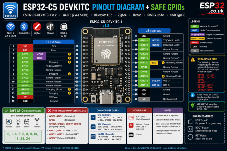
ESP32-C2 is the small brother in the ESP32 family: Wi-Fi 4 + BLE 5, RISC-V core at up to 120 MHz, and only 14 GPIOs – the ESP8684 series. In Espressif’s own docs, “ESP32-C2” and “ESP8684” are effectively the same thing.
Because the pin count is so low, you really want to know which pins are safe, which are used for boot, flash, or UART, and which can do ADC or I²C/SPI.
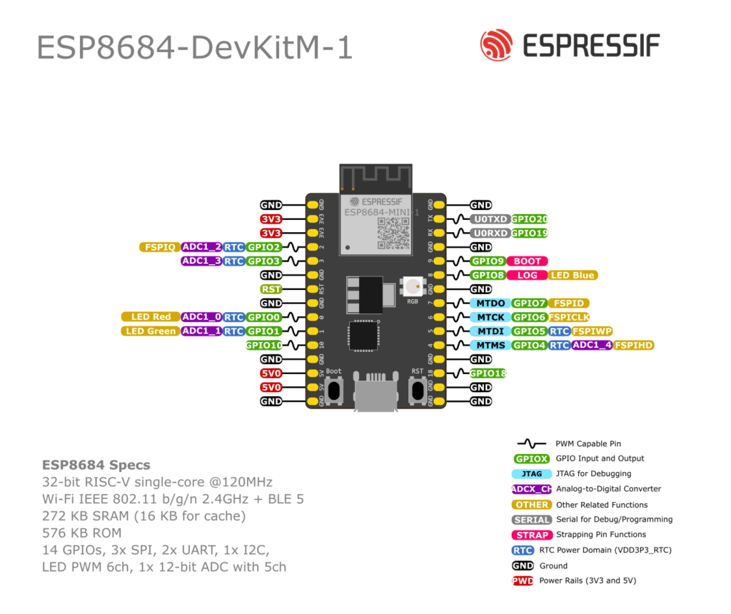
This guide focuses on the official ESP8684-DevKitC-02 (and notes for DevKitM-1) but the logic applies to most ESP32-C2 / ESP8684 boards.
1. Quick Specs & GPIO Overview
At chip level (ESP8684) you get:
- 32-bit RISC-V single-core @ up to 120 MHz
- 14 GPIO pins (GPIO0–GPIO10, GPIO18, GPIO19, GPIO20)
- Wi-Fi 4 (802.11 b/g/n) + Bluetooth LE
- 1× SAR ADC (12-bit) with analog input on GPIO0–GPIO4
- SPI, I²C, UART, PWM, timers, temperature sensor
- No capacitive touch peripheral (unlike ESP32 / S2 / S3) –
touchRead()style pins simply don’t exist.
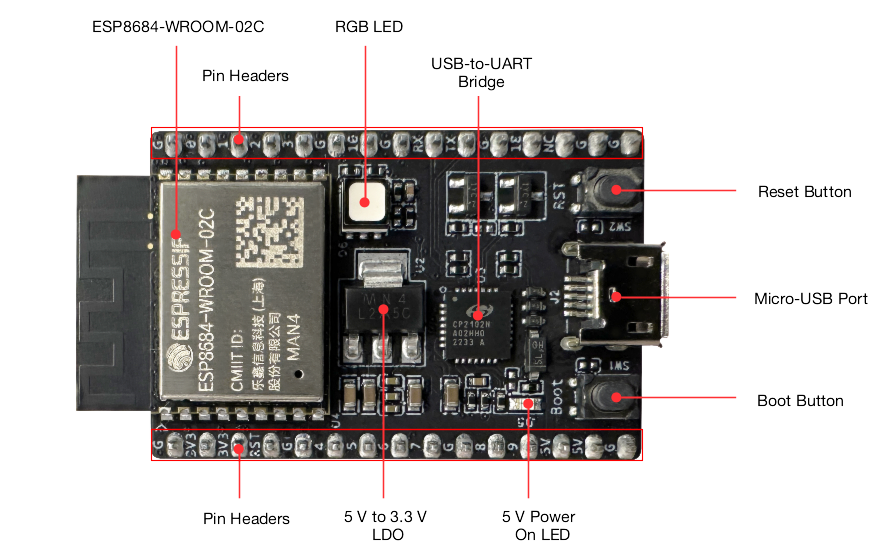
On ESP8684-DevKitC-02 most GPIOs are broken out to two headers J1 & J3.
2. Power, Ground & Control Pins
On DevKitC-02:
- 3V3 – 3.3 V output from onboard LDO (or power input if you feed 3.3 V directly).
- 5V – USB 5 V (input).
- G / GND – common ground.
- RST – reset input (CHIP_EN); pulled up by default. Driving it low resets/powers off the chip.
- BOOT button – connected so that holding BOOT while pressing RST enters the serial download boot mode (for flashing).
You normally don’t use RST or BOOT as GPIO in everyday projects.
3. Boot / Strapping Pins (GPIO8, GPIO9)
ESP8684 has two strapping pins:
- GPIO8
- GPIO9
At reset, the chip samples these pins to decide:
- Boot mode (normal flash vs UART download)
- Whether ROM boot messages are printed on UART
Key points:
- GPIO9 has an internal pull-up, so if you leave it floating it reads as “1”.
- The combination GPIO8 = 0 & GPIO9 = 0 is invalid and may cause unexpected boot behaviour.
Practical advice
- You can use GPIO8 and GPIO9 as normal GPIO after boot, but:
- Don’t hard-pull them low at reset.
- If you connect sensors, use reasonably large resistors or leave them effectively high / floating during boot.
- On DevKitC-02, GPIO8 also drives the blue LED of the onboard RGB LED.
If you’re a beginner, treat GPIO8 & GPIO9 as “advanced” pins and avoid them in your first projects.
4. Safe GPIOs for General Use
Below is a practical view of the DevKitC-02 GPIOs. (Same idea applies to DevKitM-1; pin numbers differ slightly but functions are similar.)
Recommended “safe” pins (digital I/O)
These are the easiest to use for buttons, relays, LEDs, etc.:
- GPIO0 – ADC1_CH0, Red LED; good for digital I/O / ADC.
- GPIO1 – ADC1_CH1, Green LED; general I/O / ADC.
- GPIO2 – ADC1_CH2, FSPIQ; fine for GPIO / ADC.
- GPIO3 – ADC1_CH3; good general I/O / ADC.
- GPIO18 – plain I/O, no special boot role.
- GPIO19 (RX) – default UART RX (USB-to-UART).
- GPIO20 (TX) – default UART TX.
Tips:
- GPIO0–3 & 18: safest choices for digital I/O.
- GPIO19/20: try to keep them for Serial if you want easy flashing + debugging. You can temporarily reuse them, but it complicates life.
Pins to use with care
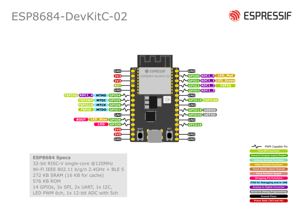
- GPIO4, 5, 6, 7, 10 – these are FSPI flash pins (FSPIHD, FSPIWP, FSPICLK, FSPID, FSPICS0). On many designs they’re wired to flash.
- They can be used via the GPIO matrix, but avoid heavy toggling or reassigning them until you know exactly what your module does.
- GPIO8 & GPIO9 – strapping pins (boot config) and also used for onboard LED blue channel (GPIO8). Use only if you understand the boot behaviour.
5. ADC Pins (Analog Inputs)
ESP32-C2 has one ADC controller (ADC1) with 12-bit resolution. The main analog-capable pins are:
| GPIO | ADC channel | Notes |
|---|---|---|
| GPIO0 | ADC1_CH0 | Also drives Red LED on DevKitC-02 |
| GPIO1 | ADC1_CH1 | Also drives Green LED |
| GPIO2 | ADC1_CH2 | Also FSPIQ |
| GPIO3 | ADC1_CH3 | Plain ADC pin |
| GPIO4 | ADC1_CH4 | Also FSPIHD |
On some DevKitM-1 revisions you might also see GPIO5 = ADC2_CH0 in the silkscreen/docs, but for most Arduino / IDF use you’ll stick to ADC1 on GPIO0–4.
Best practice
- For simple sensors (potentiometer, LDR, etc.) prefer GPIO1, GPIO2, or GPIO3.
- Add a 0.1 µF capacitor to GND close to the ADC pin to reduce noise (Espressif explicitly recommends this).
- Use attenuation appropriately (0–3.3 V usually needs 6–11 dB depending on sensor).
6. I²C Pins (Software-defined)
There are no fixed I²C pins on ESP32-C2. Any GPIO that supports digital I/O can be used as SDA/SCL via Wire.begin(SDA, SCL);.
Recommended I²C pairs (DevKitC-02)
- SDA = GPIO2, SCL = GPIO3 – great default pair
- Alternative: SDA = GPIO0, SCL = GPIO1 if you don’t mind sharing with on-board LEDs.
Avoid:
- GPIO8 & GPIO9 (boot strapping).
- GPIO19 & 20 if you want to keep them free for Serial.
- FSPI pins (4–7, 10) until you really know what you’re doing.
Example (Arduino):
#include <Wire.h>

void setup() {
  Serial.begin(115200);
  Wire.begin(2, 3); // SDA=GPIO2, SCL=GPIO3 on ESP32-C2
  Serial.println("I2C started on GPIO2 (SDA), GPIO3 (SCL)");
}

void loop() {
  // I2C sensor code here
}
7. SPI Pins
The ESP32-C2 exposes the FSPI bus (used for flash) on GPIO2, 4, 5, 6, 7, and 10:
Typical mapping:
- MOSI – GPIO7 (FSPID)
- MISO – GPIO2 (FSPIQ)
- SCK – GPIO6 (FSPICLK)
- CS – GPIO10 (FSPICS0)
- Optional HD / WP – GPIO4 / GPIO5
However…
On many modules these pins are already used by the on-board flash. Messing with them can break flash access.
Practical summary
- For most beginners, treat 4,5,6,7,10 as “reserved for flash” and avoid external SPI devices on them.
- If you must use SPI, carefully check your module’s datasheet and Espressif’s examples for ESP32-C2 with external SPI peripherals.
8. UART (Serial) Pins
Default UART0 on DevKitC-02:
- GPIO20 = U0TXD (TX) – sends data to PC via USB-UART
- GPIO19 = U0RXD (RX) – receives data from PC
This is the serial port used for:
- Programming (esptool, Arduino, etc.)
- Serial Monitor (debug prints)
You can route UART signals to other pins via the GPIO matrix, but that’s not needed in typical Arduino projects.
Example:
void setup() {
  Serial.begin(115200);   // Uses GPIO19/20 under the hood
  Serial.println("Hello from ESP32-C2 / ESP8684!");
}

void loop() {
  delay(1000);
}
If you re-purpose GPIO19/20 for other things, you’ll make flashing and debugging painful, so generally leave them alone.
9. PWM / LED Control
ESP32-C2 includes the LEDC peripheral (same concept as other ESP32 chips):
- Any normal digital GPIO can act as a PWM output.
- On DevKitC-02, the RGB LED is wired to:
- GPIO0 – Red
- GPIO1 – Green
- GPIO8 – Blue
You can drive it easily:
const int LED_RED   = 0;
const int LED_GREEN = 1;
const int LED_BLUE  = 8;

void setup() {
  pinMode(LED_RED, OUTPUT);
  pinMode(LED_GREEN, OUTPUT);
  pinMode(LED_BLUE, OUTPUT);
}

void loop() {
  digitalWrite(LED_RED, HIGH);
  digitalWrite(LED_GREEN, LOW);
  digitalWrite(LED_BLUE, LOW);
  delay(500);

  digitalWrite(LED_RED, LOW);
  digitalWrite(LED_GREEN, HIGH);
  delay(500);

  digitalWrite(LED_GREEN, LOW);
  digitalWrite(LED_BLUE, HIGH);
  delay(500);
}
Just keep in mind: GPIO8 is also a strapping pin, so avoid pulling it low during reset with strong external circuitry.
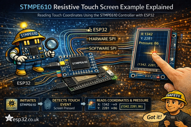
10. What About Touch Pins?
Short answer: there aren’t any.
ESP32-C2 / ESP8684 does not implement the capacitive touch controller present in classic ESP32 / ESP32-S2 / ESP32-S3.
If you need touch buttons or sliders:
- Use an external touch IC (e.g. TTP223, CAP129x, AT42QT… etc.) and connect via GPIO or I²C.
- Or pick a different chip (ESP32, S2, S3) for projects where touch is a key feature.
Trying to call touchRead() against ESP32-C2 will simply not work.
11. Minimal Example: Safe Counter + Debug Prints
A tiny example using safe pins only:
- Increment a counter
- Print to Serial
- Toggle an LED on GPIO0
// Works on ESP8684-DevKitC-02 / ESP32-C2
// LED on GPIO0, Serial on GPIO19/20

const int LED_PIN = 0;
unsigned long counter = 0;

void setup() {
  pinMode(LED_PIN, OUTPUT);
  Serial.begin(115200);
  Serial.println("ESP32-C2 / ESP8684 GPIO test starting...");
}

void loop() {
  counter++;

  // Toggle LED
  digitalWrite(LED_PIN, (counter % 2) ? HIGH : LOW);

  // Debug print
  Serial.print("Loop counter = ");
  Serial.println(counter);

  delay(500);
}
This sketch only uses:
- GPIO0 → Safe, ADC-capable, onboard LED
- UART on GPIO19/20 → default, safe
- No strapping pins, no flash pins touched
Perfect “first project” to confirm your board is wired and powered correctly.
TL;DR – Pin Selection Cheat Sheet
- Best general-purpose GPIOs: 0, 1, 2, 3, 18
- Keep for Serial if possible: 19 (RX), 20 (TX)
- ADC inputs: 0–4 (ADC1_CH0…CH4)
- Strapping (boot) pins: 8, 9 → use only with care
- Flash / FSPI pins (avoid): 4, 5, 6, 7, 10
- No built-in touch – use external touch IC or another ESP chip if you need touch sensing.