This guide focuses on pinout and GPIO selection for the DevKitC-1, so you can safely connect sensors, relays, USB, displays etc. without running into weird boot issues.
The ESP32-S3-DevKitC-1 is Espressif’s entry-level development board for the ESP32-S3-WROOM-1 / 1U / 2 modules – a Wi-Fi + Bluetooth LE SoC with dual-core CPU, vector instructions for AI, and plenty of GPIOs.
Scope: This article targets the official ESP32-S3-DevKitC-1 board as documented by Espressif (J1/J3 pin headers).
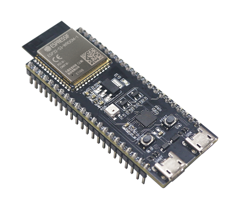
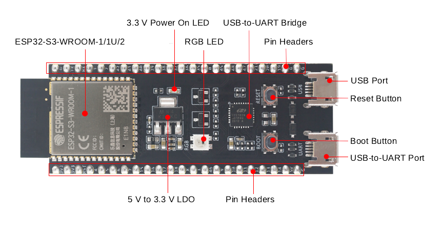
1. Board overview
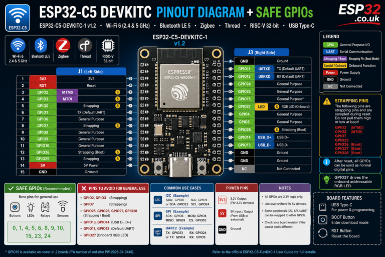
On ESP32-S3-DevKitC-1, Espressif breaks out all available GPIOs except the internal flash bus to two 22-pin headers: J1 and J3.
Key onboard components:
- ESP32-S3-WROOM-1 / 1U / 2 module (Wi-Fi + BT LE, 8–32 MB flash, optional PSRAM)
- 5 V → 3.3 V LDO regulator
- USB-to-UART port (Micro-USB) – power + serial + flashing
- Native ESP32-S3 USB port – USB 1.1 OTG (device/host + JTAG)
- BOOT button – enter download mode (when combined with RESET)
- RESET (EN) button – resets the chip
- Addressable RGB LED on GPIO48
- 3.3 V power LED
For some board variants with Octal SPI flash/PSRAM, GPIO35, GPIO36 and GPIO37 are internally used for flash/PSRAM and not available externally, even though they appear in generic pin maps.
2. Power supply options
The DevKitC-1 supports three mutually exclusive power inputs:
- USB-to-UART port (Micro-USB) – default/recommended
- ESP32-S3 USB port (native USB)
- Header pins
- 5V + GND – feed 5 V to onboard LDO
- 3V3 + GND – feed regulated 3.3 V directly
Practical rules:
- For development: just use the USB-to-UART port; it powers and exposes serial.
- If using the 5V pin, supply a stable 5 V (e.g. DC/DC buck from 12 V).
- If using 3V3, your external regulator must handle Wi-Fi peaks.
Logic level on GPIOs is always 3.3 V – do not feed 5 V into any GPIO.
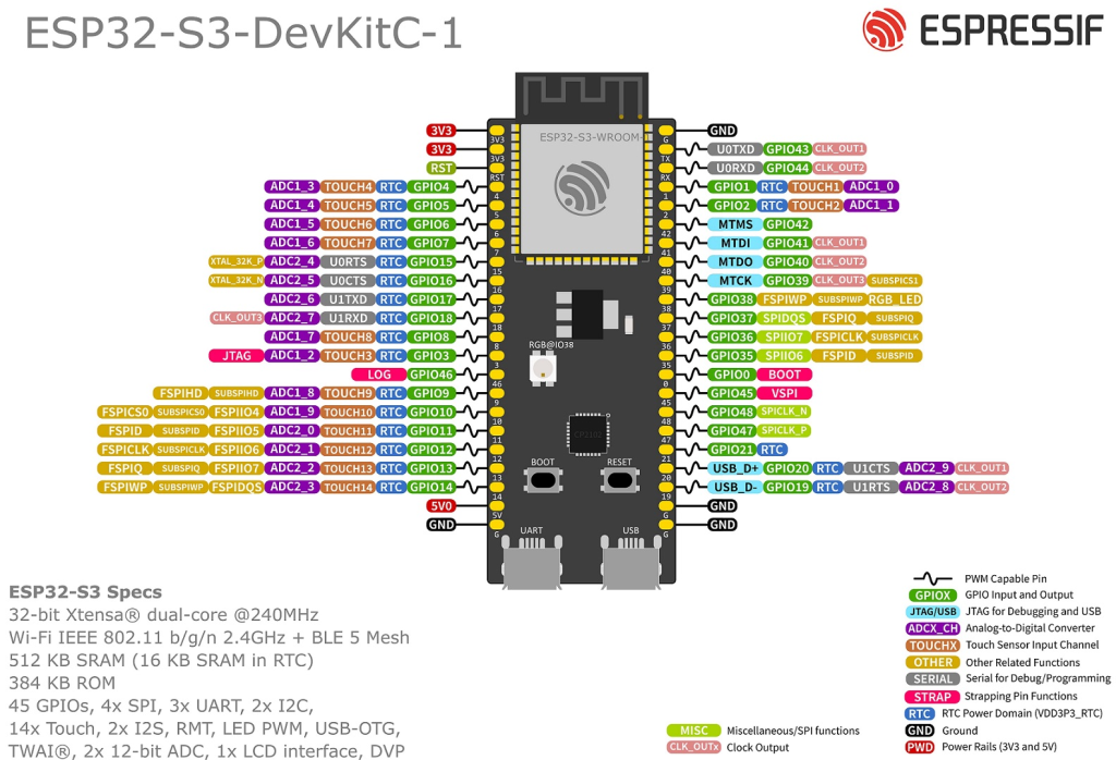
3. ESP32-S3 GPIO basics
The ESP32-S3 SoC exposes 45 GPIOs (GPIO0–21 and GPIO26–48; 22–25 don’t exist).
On the DevKitC-1
- Most GPIOs are brought out on J1/J3
- GPIO43 (TX) and GPIO44 (RX) are wired to the USB-to-UART bridge
- GPIO48 drives the on-board RGB LED
- For some module variants, GPIO35–37 are reserved for internal Octal flash/PSRAM (not for external use)
GPIOs are multiplexed: any given pin can often be digital I/O, ADC, touch, I²C, SPI, UART, PWM, etc., routed through the IO matrix.
4. Strapping pins – pins that affect boot
ESP32-S3 has four strapping pins that are sampled at reset to decide boot mode, flash voltage and JTAG source:
- GPIO0 – boot mode (firmware from flash vs download mode)
- GPIO46 – boot mode + ROM message printing
- GPIO45 – VDD_SPI voltage (3.3 V vs 1.8 V for flash/PSRAM)
- GPIO3 – JTAG signal source selection
What this means in practice:
- If you pull these pins strongly HIGH/LOW at reset, you can:
- Force download mode instead of normal boot (GPIO0/46)
- Misconfigure flash voltage (GPIO45) and potentially break boot
- Confuse JTAG configuration (GPIO3)
Recommendation:
For mainstream projects, avoid using GPIO0, GPIO3, GPIO45, GPIO46 except as very carefully-designed inputs/jumpers.
5. “Safe” everyday GPIOs on DevKitC-1
From the official header tables (J1/J3) and GPIO restrictions, we can define a safe default set of pins for digital I/O, PWM etc.
5.1 Good general-purpose GPIOs
These are usually free of boot/flash quirks and available on the DevKitC-1:
- GPIO1, 2, 4, 5, 6, 7, 8, 9, 10
- GPIO11, 12, 13, 14, 15, 16, 17, 18
- GPIO19, 20, 21
- GPIO38, 39, 40, 41, 42
- GPIO33, 34
- GPIO43, 44 (though used by UART0)
- GPIO47, 48 (48 is tied to RGB LED)
Notes:
- On some ESP32-S3-WROOM-1/2 variants with Octal memory, GPIO35–37 are used internally → don’t rely on them unless you check your exact module code.
- GPIO43/44 are shared with USB-to-UART bridge; you can still use them, but heavy external loading will affect flashing/Serial.
5.2 Pins to treat with caution
- Strapping pins – GPIO0, 3, 45, 46 (boot/JTAG/VDD_SPI)
- Internally used flash/PSRAM pins – GPIO35–37 on Octal variants
- USB D± pins – GPIO19 (USB_D-), GPIO20 (USB_D+) when using native USB
6. ADC pins (analog inputs)
ESP32-S3 includes two 12-bit SAR ADCs with 20 channels:
- ADC1 (10 channels): GPIO1–10
- ADC2 (10 channels): GPIO11–20
Key points:
- Resolution: 12 bits (0–4095) by default
- Usable voltage range depends on attenuation; typical range up to about 2.5–3.0 V for the default 11 dB setting – keep input ≤ 3.3 V.
- Some Arduino/ESP-IDF stacks still treat ADC2 as shared with Wi-Fi, so for maximum robustness in Wi-Fi-heavy projects it’s safest to prefer ADC1 (GPIO1–10).
6.1 Recommended ADC pins on DevKitC-1
Best choices (ADC1, Wi-Fi-friendly):
- GPIO1 → ADC1_CH0
- GPIO2 → ADC1_CH1
- GPIO3 → ADC1_CH2 (strapping – avoid unless you know what you’re doing)
- GPIO4–10 → ADC1_CH3–9
ADC2 (11–20) are usable, but:
- They may conflict with Wi-Fi in certain frameworks
- GPIO19 and GPIO20 double as USB D-/D+ – don’t use as ADC if native USB is active
7. Touch sensor pins
ESP32-S3 has multiple capacitive touch pads (TOUCH1–TOUCH14) mapped to GPIOs 1–14 (plus 3,4,… etc – see IO list).
On the DevKitC-1, common touch-capable GPIOs include:
- GPIO1–10 (TOUCH1–TOUCH10)
- GPIO3 (TOUCH3)
- GPIO4–8, 9, 10 (TOUCH4–10)
- GPIO11–14 (TOUCH11–14)
Good practical choices (avoid strapping pins):
- GPIO4, 5, 6, 7, 8, 9, 10, 11, 12, 13, 14
Use touchRead(pin) (Arduino) or the ESP-IDF touch driver to read values and configure touch wake from deep sleep.
8. USB pins (native USB D+ / D-)
Unlike the classic ESP32, the S3 has native USB 2.0 Full-Speed OTG. On DevKitC-1, the USB signals are mapped to:
- GPIO20 → USB_D+ (also ADC2_CH9, U1CTS, CLK_OUT1)
- GPIO19 → USB_D- (also ADC2_CH8, U1RTS, CLK_OUT2)
They are routed to the ESP32-S3 USB port.
Practical rules:
- If you use TinyUSB / native USB (CDC, HID, MIDI, etc.), treat GPIO19/20 as dedicated USB pins.
- Don’t connect external circuits to these pins while using the USB connector.
- If you’re not using native USB, they behave as normal GPIO/ADC – but be careful not to short them when a USB cable is plugged.
9. I²C pins
ESP32-S3 can route I²C signals to almost any GPIO via the IO matrix.
For simplicity and consistency across projects, a sensible default choice on DevKitC-1 is:
| Function | Recommended GPIO | Reason |
|---|---|---|
| SDA | GPIO8 | On J1, ADC1, touch, no special boot role |
| SCL | GPIO9 | On J1, ADC1, touch, also used in examples |
Example (Arduino):
#include <Wire.h>

void setup() {
  Wire.begin(8, 9);  // SDA = GPIO8, SCL = GPIO9
}
Other combinations are possible, but avoid:
- GPIO0, 3, 45, 46 (strapping)
- Pins used for USB (19/20) if you actually use native USB
- GPIO35–37 on Octal memory variants
10. SPI pins
The ESP32-S3 has multiple SPI controllers. One is dedicated to the internal flash/PSRAM (using FSPI pins like GPIO35–38 on some modules); others (e.g. SPI2/3) are available for user devices.
On DevKitC-1 the J3 header exposes a nice cluster of FSPI-capable pins:
- GPIO38 – FSPIWP / SUBSPIWP
- GPIO37 – SPIDQS / FSPIQ
- GPIO36 – SPIIO7 / FSPICLK
- GPIO35 – SPIIO6 / FSPID
These are ideal as a high-speed SPI bus when they’re not used internally by Octal flash/PSRAM (check your module variant).
A typical user-SPI mapping that works well on common N8R8 boards:
| Signal | Recommended GPIO |
|---|---|
| SCK | GPIO36 |
| MISO | GPIO37 |
| MOSI | GPIO35 |
| CS | GPIO38 |
If you have an Octal memory variant where these pins are internal, pick another run of “safe” GPIOs (e.g. 11–14 or 4–7) and route them as SPI via the GPIO matrix.
11. UART / Serial pins
ESP32-S3 has three UART controllers.
On DevKitC-1, the default mapping is:
- UART0 (console / flashing)
- TX0 → GPIO43 (TX pin on J3)
- RX0 → GPIO44 (RX pin on J3)
- Other UARTs (UART1/2) can be mapped to any suitable GPIO via IO matrix (e.g. 16/17, 19/20, etc.)
Recommendations:
- Leave GPIO43/44 primarily for Serial console and flashing.
- For an extra hardware Serial (GPS, RS-485, etc.):
- choose a pair from safe pins (e.g. GPIO17 = TX, GPIO16 = RX)
- configure via
Serial1.begin(baud, config, RX, TX)(Arduino) or UART driver in ESP-IDF.
12. Practical pin recipes for ESP32-S3-DevKitC-1
12.1 Classic Wi-Fi sensor + relay node
Ready-to-reuse pattern:
| Function | Recommended GPIOs | Notes |
|---|---|---|
| I²C SDA | GPIO8 | BME280, OLED, etc. |
| I²C SCL | GPIO9 | |
| Relay output | GPIO33 or GPIO34 | Far from strapping / USB pins |
| Extra digital input | GPIO38 or GPIO39 | Button, reed switch |
| Analog sensor input | GPIO1 / 2 / 4 / 5 | ADC1, safe with Wi-Fi |
12.2 USB gadget (HID/CDC/MIDI) with status LED & button
| Function | Recommended GPIOs | Notes |
|---|---|---|
| USB D+ / D- | GPIO20 / GPIO19 | Via native USB port |
| Status RGB LED | GPIO48 | On-board LED |
| User button | GPIO4 or GPIO5 | Optional touch + digital input |
13. Summary – ESP32-S3-DevKitC-1 “rules of thumb”
Compared to a classic ESP32 DevKit, the ESP32-S3-DevKitC-1 gives you Bluetooth LE + native USB + better ADC, but you must respect a few rules:
- Avoid strapping pins for normal I/O
→ GPIO0, 3, 45, 46 (boot, VDD_SPI, ROM printing, JTAG). - Treat USB pins specially
→ GPIO19 (USB_D-), GPIO20 (USB_D+) – don’t share with other circuitry when using native USB. - Watch out for internal flash/PSRAM pins
→ On Octal variants, GPIO35–37 are not for external use. - Prefer ADC1 for Wi-Fi projects
→ Use GPIO1–10 for analog sensors; ADC2 (11–20) may clash with Wi-Fi in some stacks. - Use a “safe” GPIO pool
→ For general I/O: 1, 2, 4–10, 11–18, 19–21, 33–34, 38–42, 43–44, 47–48 on non-Octal variants.
Follow these and the S3-DevKitC-1 becomes a very predictable board for Wi-Fi sensors, USB devices, Home Assistant nodes, and general ESP32-S3 experiments – with minimal “why the hell won’t it boot?” moments.