Quick Summary :
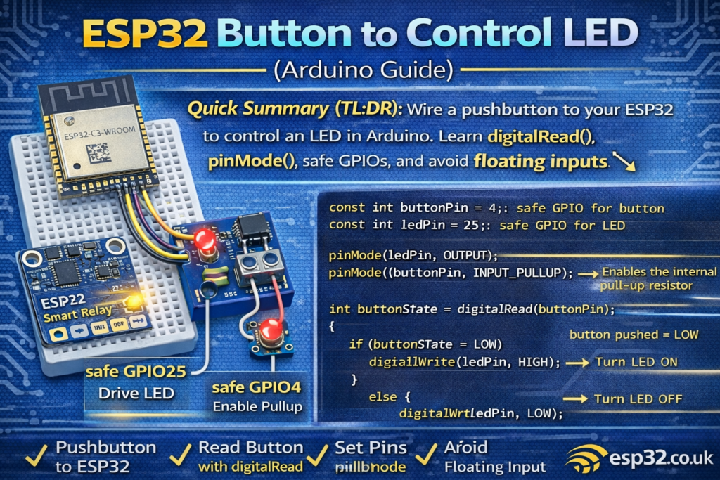
This beginner guide explains how to wire a pushbutton to an ESP32 and use it to control an LED. You’ll learn what digitalRead() returns, why pinMode() matters, and how to avoid the most common beginner issue: a floating input (random button presses).
ESP32 Button to Control LED (Arduino Guide)
A button example is the next step after Blink. Instead of turning an LED on/off every second, you’ll turn it on only when you press a button.
Here’s the code:
// constants won't change. They're used here to set pin numbers:
const int buttonPin = 2;  // the number of the pushbutton pin
const int ledPin = 13;    // the number of the LED pin

// variables will change:
int buttonState = 0;  // variable for reading the pushbutton status

void setup() {
  // initialize the LED pin as an output:
  pinMode(ledPin, OUTPUT);
  // initialize the pushbutton pin as an input:
  pinMode(buttonPin, INPUT);
}

void loop() {
  // read the state of the pushbutton value:
  buttonState = digitalRead(buttonPin);

  // check if the pushbutton is pressed. If it is, the buttonState is HIGH:
  if (buttonState == HIGH) {
    // turn LED on:
    digitalWrite(ledPin, HIGH);
  } else {
    // turn LED off:
    digitalWrite(ledPin, LOW);
  }
}
Let’s make this understandable for complete beginners, and also show the correct wiring so it works reliably on an ESP32.
1) What this project does
- The ESP32 checks the button pin.
- If the button is pressed, the ESP32 turns the LED on.
- If the button is not pressed, the ESP32 turns the LED off.
That’s it.
2) Hardware you need
- ESP32 dev board
- Pushbutton (momentary)
- LED + resistor (220Ω to 1kΩ) (optional if your board has an on-board LED)
- Jumper wires / breadboard
3) Wiring (IMPORTANT: avoid floating inputs)
The code uses:
buttonPin = 2ledPin = 13
ESP32 pin warning
On many ESP32 boards:
- GPIO 2 often controls the on-board LED and can be a boot-related pin.
- GPIO 13 may not exist on some dev boards, or it’s not connected to an LED.
So the code is conceptually fine, but for ESP32 beginners it’s better to use safer pins:
✅ Recommended for examples:
- Button: GPIO4
- LED: GPIO25 (or on-board LED if you know the pin)
We’ll explain both: Example version and the “ESP32-safe” version.
3.1 Correct button wiring (two options)
Option A (recommended): Button to GND + internal pull-up
This avoids floating inputs with no extra resistor.
- One side of button → GPIO4
- Other side → GND
Then use INPUT_PULLUP in code (shown below).
Option B: Button to 3.3V + external pull-down resistor
- Button side → 3V3
- Other side → GPIO
- Add a 10kΩ resistor from GPIO → GND
This works too, but Option A is simpler.
Why this matters: if you use
pinMode(buttonPin, INPUT)with no pull-up or pull-down, the pin “floats” and reads random HIGH/LOW values.
4) Code explanation (line by line)
4.1 Constants
const int buttonPin = 2;
const int ledPin = 13;
These are just names for the pins you’re using.
4.2 Variable
int buttonState = 0;
This stores the result of digitalRead(). It will be either HIGH or LOW.
4.3 setup()
pinMode(ledPin, OUTPUT);
pinMode(buttonPin, INPUT);
- LED pin is set to OUTPUT (we will drive it HIGH/LOW)
- Button pin is set to INPUT (we read it)
4.4 loop()
buttonState = digitalRead(buttonPin);
Reads the pin:
- returns
HIGHif it sees 3.3V - returns
LOWif it sees 0V (GND)
Then:
if (buttonState == HIGH) {
  digitalWrite(ledPin, HIGH);
} else {
  digitalWrite(ledPin, LOW);
}
If pressed → LED ON
Else → LED OFF
5) The ESP32-safe version
This is the version that works reliably and avoids beginner pain.
Wiring (recommended)
- Button between GPIO4 and GND
- LED + resistor from GPIO25 to GND
Code
const int buttonPin = 4;   // safe GPIO for button
const int ledPin = 25;     // safe GPIO for LED

void setup() {
  pinMode(ledPin, OUTPUT);

  // internal pull-up enabled, so pin reads HIGH normally
  // and LOW when button is pressed (button to GND)
  pinMode(buttonPin, INPUT_PULLUP);
}

void loop() {
  int buttonState = digitalRead(buttonPin);

  // pressed = LOW because of INPUT_PULLUP
  if (buttonState == LOW) {
    digitalWrite(ledPin, HIGH);
  } else {
    digitalWrite(ledPin, LOW);
  }
}
Why this is better:
- No floating input
- No extra resistor needed
- Uses safe pins that rarely cause boot issues
6) Common beginner problems (and fixes)
“My LED randomly turns on/off without pressing anything”
Cause: floating input (INPUT with no pull-up/down)
Fix: use INPUT_PULLUP (recommended) or add an external resistor.
“My button works backwards (LED on when not pressed)”
That’s normal with INPUT_PULLUP:
- not pressed = HIGH
- pressed = LOW
Just invert the logic (like in the recommended version above).
“ESP32 won’t boot after wiring the button”
Some pins affect boot. Avoid:
- GPIO0, GPIO2, GPIO12, GPIO15
Use GPIO4 or GPIO25/26/27/32/33 instead.
7) Next step: toggle the LED (press once = change state)
Right now the LED only stays on while you hold the button. The next beginner upgrade is “toggle” mode:
- press once → LED ON
- press again → LED OFF