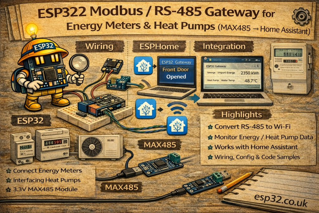
A huge amount of serious home energy hardware speaks Modbus RTU over RS-485:
- DIN-rail energy meters (e.g. SDM120, SDM630, DDSU666, etc.)
- Heat pumps, boilers, inverters, BMS controllers
- Industrial sensors and controllers
With one ESP32 and a cheap MAX485 (RS-485) transceiver, you can build a gateway that:
- Polls Modbus registers (voltage, current, power, kWh, temperatures, alarms)
- Publishes the values into Home Assistant
- Works fully local, no cloud
This guide covers:
- Wiring an ESP32 to RS-485 (MAX485)
- Modbus basics (address, baud rate, registers)
- ESPHome Modbus configuration (recommended)
- MQTT/Arduino alternative (optional)
- Practical tips for SDM120/SDM630 and heat pump integrations
1. Modbus RTU & RS-485 in 2 minutes
- RS-485 = physical layer (differential wires A/B, long distance, noise resistant)
- Modbus RTU = protocol running over RS-485
- One master (ESP32 gateway) polls one or more slaves (meter / heat pump)
- Slaves have:
- Address (1…247)
- Baud rate (commonly 9600)
- Parity/stop bits (often 8N1 or 8E1)
- Data lives in registers:
- Input registers (read-only)
- Holding registers (read/write)
- Values are often:
- 16-bit or 32-bit
- Scaled (e.g. “2305” means 230.5 V)
- Sometimes floats (IEEE 754)
2. Hardware Required
- ESP32 DevKit
- MAX485 module (or equivalent RS-485 TTL transceiver)
- RS-485 cable to meter / heat pump (twisted pair recommended)
- Optional: 120 Ω termination resistor (only at bus ends)
- Power supply for ESP32 (5 V USB is fine)
Important note about voltage levels:
- MAX485 modules typically run from 5 V (some are 3.3 V tolerant, many are not)
- The ESP32 UART pins are 3.3 V
- In practice, many MAX485 boards work with ESP32 without issues, but for “proper” engineering:
If you want the safest choice: buy a MAX3485 / SP3485 “3.3 V RS485” module.
3. Wiring ESP32 ↔ RS-485 (MAX485)
MAX485 module pins typically:
- VCC, GND
- RO (Receiver Output)
- DI (Driver Input)
- RE (Receiver Enable) – active LOW
- DE (Driver Enable) – active HIGH
- A, B (RS-485 differential pair)
3.1 Recommended ESP32 Wiring (Half-Duplex)
Use one UART (example GPIO16/17) + one direction control GPIO:
ESP32                 MAX485
-----                 ------
5V   ---------------- VCC
GND  ---------------- GND

GPIO17 (TX) --------- DI
GPIO16 (RX) --------- RO

GPIO4  -------------  DE and RE (tied together)
                      (DE=HIGH transmit, RE=LOW receive)

RS-485 A ------------ A
RS-485 B ------------ B
Direction control:
- Many libraries (and ESPHome) support a “flow control pin” to toggle transmit/receive.
- Often you connect:
- DE and RE together
- Drive them with a single GPIO
If your module labels RE as RE/ or ~RE, remember it’s inverted (active low).
4. RS-485 Bus Tips (Avoid Pain)
- Use a twisted pair for A/B
- Keep GND reference if possible (some devices need it)
- Termination:
- Only needed at long distances / high speed
- If used, place 120 Ω across A/B at the two ends of the bus
- Bias resistors:
- Some buses need pull-up/pull-down biasing (often built into equipment)
- If values are garbage:
- A/B swapped is common → just swap them and retry
METHOD 1 — ESPHome Modbus Gateway (Recommended)
ESPHome can talk Modbus RTU and expose sensors directly into Home Assistant.
5. ESPHome Base Config + UART
esphome:
  name: esp32-modbus-gateway
  platform: ESP32
  board: esp32dev

wifi:
  ssid: "YOUR_WIFI"
  password: "YOUR_PASSWORD"

logger:
api:
ota:

uart:
  id: modbus_uart
  tx_pin: 17
  rx_pin: 16
  baud_rate: 9600
  stop_bits: 1
If your device uses parity (common on some meters), add:
parity: EVEN
6. Add Modbus Layer + Controller
modbus:
  id: modbus1
  uart_id: modbus_uart
  flow_control_pin: 4   # DE/RE control pin
Now define a controller per slave address:
modbus_controller:
  - id: sdm120
    address: 1
    modbus_id: modbus1
    setup_priority: -10
    update_interval: 5s
7. Example: SDM120 (Single Phase Meter)
SDM meters have well-known register maps (you’ll match to your manual).
Below is a typical pattern for voltage, current, power, energy (register numbers vary by model/firmware; verify in your SDM120 documentation).
sensor:
  - platform: modbus_controller
    modbus_controller_id: sdm120
    name: "SDM120 Voltage"
    id: sdm120_voltage
    register_type: holding
    address: 0x0000
    unit_of_measurement: "V"
    accuracy_decimals: 1
    value_type: FP32

  - platform: modbus_controller
    modbus_controller_id: sdm120
    name: "SDM120 Current"
    register_type: holding
    address: 0x0006
    unit_of_measurement: "A"
    accuracy_decimals: 2
    value_type: FP32

  - platform: modbus_controller
    modbus_controller_id: sdm120
    name: "SDM120 Active Power"
    register_type: holding
    address: 0x000C
    unit_of_measurement: "W"
    accuracy_decimals: 1
    value_type: FP32

  - platform: modbus_controller
    modbus_controller_id: sdm120
    name: "SDM120 Energy Import"
    register_type: holding
    address: 0x0156
    unit_of_measurement: "kWh"
    accuracy_decimals: 2
    value_type: FP32
Key fields explained:
address:is the Modbus register addressregister_type:holding vs input (depends on device)value_type: FP32means 32-bit floatupdate_interval:in controller controls polling rate
If your meter uses input registers, change:
register_type: input
8. Example: SDM630 (Three Phase Meter)
You typically read per-phase voltage/current + total power + total energy.
Set controller address (example 2):
modbus_controller:
  - id: sdm630
    address: 2
    modbus_id: modbus1
    update_interval: 5s
Then define sensors similarly:
- Voltage L1/L2/L3
- Current L1/L2/L3
- Total active power
- Total import/export kWh
(Exact register addresses depend on your SDM630 map.)
9. Example: Heat Pump via Modbus
Heat pumps commonly expose:
- Flow temperature
- Return temperature
- Outdoor temp
- Compressor frequency
- Mode (heat/cool/dhw)
- Alarms
The structure is the same:
- Set the correct Modbus address, baud rate, parity
- Read registers based on the vendor map
- Apply scaling (sometimes ×0.1 or ×0.01)
If a register holds “235” meaning 23.5°C, you use filters:
filters:
  - multiply: 0.1
Example:
sensor:
  - platform: modbus_controller
    modbus_controller_id: heatpump
    name: "Heat Pump Flow Temp"
    register_type: input
    address: 0x0100
    unit_of_measurement: "°C"
    accuracy_decimals: 1
    value_type: U_WORD
    filters:
      - multiply: 0.1
METHOD 2 — Arduino + MQTT Modbus Gateway (Alternative)
If you prefer “raw MQTT”:
- ESP32 reads Modbus registers with a library like ModbusMaster
- Builds JSON payload
- Publishes to MQTT topic like
home/modbus/sdm120
Example payload:
{
  "voltage": 230.4,
  "current": 1.82,
  "power": 412.0,
  "energy_kwh": 18.25
}
Home Assistant then uses the same mqtt: sensor: pattern you already use.
This method is flexible but requires more code and careful error handling.
10. Home Assistant Integration Ideas
10.1 Energy Dashboard
If you publish/import kWh correctly, you can feed Home Assistant’s Energy Dashboard (especially if you have solar / battery).
10.2 Alerts
- Notify if power draw exceeds a threshold
- Notify if heat pump reports an alarm register
- Notify if voltage drops below a safe level
10.3 Logging & Stats
Once data is in HA, it becomes part of:
- history graphs
- statistics
- long-term energy monitoring
11. Troubleshooting Checklist (Most Common Failures)
- A/B swapped: swap them if no response
- Wrong baud/parity: check device manual (9600 8N1 vs 9600 8E1 is common)
- Wrong slave address: many meters default to 1, but not always
- No direction control: ensure DE/RE pin is working if using MAX485
- Register map mismatch: SDM models differ; confirm addresses and data types
- Float word order: some devices swap 16-bit words (endianness). ESPHome supports different
value_typevariants if needed.
Summary
An ESP32 + RS-485 transceiver turns Modbus RTU devices into Home Assistant entities:
- Works for DIN energy meters like SDM120/SDM630 and many heat pumps
- ESPHome is the easiest path: UART + modbus + modbus_controller + sensors
- Once values are in HA, you can build dashboards, automations, and energy insights
The key is matching:
- slave address
- baud/parity
- register map + data type + scaling
Get those right and Modbus becomes one of the most powerful “serious hardware” integrations you can add to Home Assistant.